Page Contents
- 1 MIRRORS
- 2 Inside Day/Night Mirror
- 2.1 Automatic Dimming Inside Mirror — If Equipped
- 2.2 Outside Mirrors
- 2.3 Exterior Mirrors Folding Feature — If Equipped
- 2.4 Outside Mirror Auto Dimmer — If Equipped
- 2.5 Outside Mirrors with Turn Signal & Approach Lighting — If Equipped
- 2.6 Tilt in Reverse Feature — If Equipped
- 2.7 Power Remote Control Mirrors
- 2.8 Heated Remote Control Mirrors — If Equipped
- 2.9 Illuminated Vanity Mirrors — If Equipped
- 3 HANDS–FREE COMMUNICATION (UConnect™) — IF EQUIPPED
- 4 SEATS
- 5 DRIVER MEMORY SEAT — IF EQUIPPED
- 6 TO OPEN AND CLOSE THE HOOD
- 7 LIGHTS
- 7.1 Headlight Switch
- 7.2 Automatic Headlights – If Equipped
- 7.3 Headlights On with Wipers (Available with Auto Headlights Only)
- 7.4 SmartBeams — If Equipped
- 7.5 Headlight Time Delay
- 7.6 Daytime Running Lights (Canada Only)
- 7.7 Lights-on Reminder
- 7.8 Fog Lights — If Equipped
- 7.9 Multi-Function Lever
- 7.10 Overhead Console Map/Reading Lights
- 7.11 Interior Lights
- 8 WINDSHIELD WIPERS AND WASHERS
- 9 HEADLIGHT WASHERS — IF EQUIPPED
- 10 TILT/TELESCOPING STEERING COLUMN
- 11 POWER TILT/TELESCOPING STEERING COLUMN — IF EQUIPPED
- 12 ADJUSTABLE PEDALS — IF EQUIPPED
- 13 ELECTRONIC SPEED CONTROL
- 14 ADAPTIVE CRUISE CONTROL (ACC) — IF EQUIPPED
- 14.1 Adaptive Cruise Control (ACC) Operation
- 14.2 Activating Adaptive Cruise Control (ACC)
- 14.3 To Activate:
- 14.4 To Set a Desired Speed:
- 14.5 To Cancel:
- 14.6 To Turn Off:
- 14.7 To Resume Speed:
- 14.8 To Vary the Speed Setting:
- 14.9 Setting the Following Distance in ACC
- 14.10 Adaptive Cruise Control (ACC) Menu
- 14.11 Display Warnings & Maintenance
- 14.12 Precautions While Driving with ACC
- 14.13 General Information
- 15 REAR PARK ASSIST SYSTEM — IF EQUIPPED
- 16 OVERHEAD CONSOLE
- 17 GARAGE DOOR OPENER (HomeLink) — IF EQUIPPED
- 18 POWER SUNROOF — IF EQUIPPED
- 19 ELECTRICAL POWER OUTLETS
- 20 CUP HOLDERS
- 21 STORAGE
- 22 LOAD LEVELING SYSTEM — IF EQUIPPED
MIRRORS
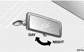
Inside Day/Night Mirror
Adjust the mirror to center on the view through the rear window. A two-point pivot system allows for horizontal and vertical mirror adjustment.
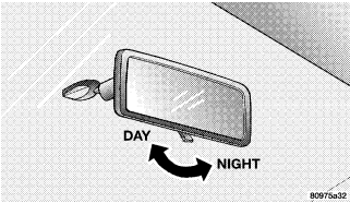
Annoying headlight glare can be reduced by moving the small control under the mirror to the night position (toward rear of vehicle). The mirror should be adjusted while set in the day position (toward windshield).
Automatic Dimming Inside Mirror — If Equipped
This mirror automatically adjusts for annoying headlight glare from vehicles behind you. You can turn the feature on or off by pressing the button at the base of the mirror. A light in the button will indicate when the dimming feature is activated.

CAUTION! To avoid damage to the mirror during cleaning, never spray any cleaning solution directly onto the mirror. Apply the solution onto a clean cloth and wipe the mirror clean.
Outside Mirrors
To receive maximum benefit, adjust the outside mirror(s) to center on the adjacent lane of traffic and a slight overlap of the view obtained from the inside mirror.
NOTE: The passenger side convex outside mirror will give a much wider view to the rear, and especially of the lane next to your vehicle.
WARNING! Vehicles and other objects seen in the passenger side convex mirror will look smaller and farther away than they really are. Relying too much on your passenger side convex mirror could cause you to collide with another vehicle or other object. Use your inside mirror when judging the size or distance of a vehicle seen in the passenger side convex mirror.
Exterior Mirrors Folding Feature — If Equipped
Some models have exterior mirrors that are hinged. The hinge allows the mirror to pivot forward and rearward to resist damage. The hinge has three detent positions, full forward, full rearward, and normal.
Outside Mirror Auto Dimmer — If Equipped
This mirror automatically adjusts for annoying headlight glare from vehicles behind you. You can turn this feature on or off by pressing the button at the base of the Inside Rearview Mirror. This feature is also available on the passenger outside mirror of mirrors equipped with turn signal and approach lighting.
Outside Mirrors with Turn Signal & Approach Lighting — If Equipped
Driver and passenger outside mirrors with turn signal and approach lighting contain four LEDs, which are located in the upper outer corner of each mirror. Three of the LEDs are turn signal indicators, which flash with the corresponding turn signal lights in the front and rear of the vehicle. Turning on the hazard flashers will also activate these LEDs. The fourth (uppermost) LED supplies illuminated entry lighting, which turns on in both mirrors when you use the keyless entry transmitter or open any door. This LED shines outward to illuminate the front and rear door handles. It also shines downward to illuminate the area in front of the doors. The illuminated entry lighting fades to off after about 30 seconds or it will fade to off immediately once the ignition switch is turned ON from the LOCK position. NOTE: The approach lighting will not function when the gear selector lever is moved out of the P (PARK) position.
Tilt in Reverse Feature — If Equipped
The Tilt in Reverse feature tilts the outside rearview mirrors downward when the ignition switch is in the ON position and the transmission is in the R (Reverse) position. This feature provides the driver with a better view of the ground and vehicle in the area of the rear tires when backing up. The mirrors will move back to their previous position when the transmission is shifted out of R (Reverse). The Tilt in Reverse feature can be enabled or disabled through the Electronic Vehicle Information Center (EVIC) — if equipped. For details, “Personal Settings (Customer Programmable Features)” under “Electronic Vehicle Information Center (EVIC)” in Section 4 of this manual.
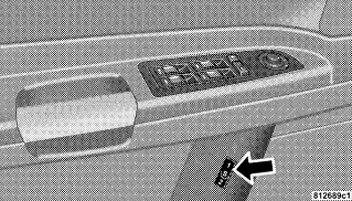
Power Remote Control Mirrors
The power mirror switch is located on the driver’s door trim panel next to the power door lock switch. A rotary knob selects the left mirror, right mirror, or off position.
After selecting a mirror, move the knob in the same direction you want the mirror to move. Use the center off position to guard against accidentally moving a mirror position.

NOTE: For vehicles equipped with Driver Memory Seat, you can use your remote keyless entry transmitter or the memory switch on the driver’s door panel to return the power mirrors to pre-programmed positions. “Driver Memory Seat” in this section for details.
Heated Remote Control Mirrors — If Equipped
These mirrors are heated to melt frost or ice. This feature is activated whenever you turn on the Rear Window Defrost.
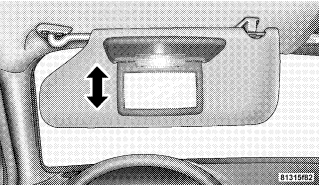
Illuminated Vanity Mirrors — If Equipped
An illuminated vanity mirror is on the sun visor. To use the mirror, rotate the sun visor downward and swing the mirror cover upward. The light turns on automatically. Closing the mirror cover turns off the lights.
HANDS–FREE COMMUNICATION (UConnect™) — IF EQUIPPED
UConnect™ is a voice-activated, hands-free, in- vehicle communications system. UConnect™ allows you to dial a phone number with your cellular phone using simple voice commands (e.g., Call” “Mike” ”Work or Dial” “248-555-1212). Your cellular phone’s audio is transmitted through your vehicle’s audio system; the system will automatically mute your radio when using the UConnect™ system. NOTE: The UConnect™ system use requires a cellular phone equipped with the Bluetooth Hands-Free Profile, version 0.96 or higher. See www.chrysler.com/uconnect for supported phones. UConnect™ allows you to transfer calls between the system and your cellular phone as you enter or exit your vehicle, and enables you to mute the system’s microphone for private conversation. The UConnect™ phonebook enables you to store up to 32 names and four numbers per name. Each language has a separate 32-name phonebook accessible only in that language. This system is driven through your Bluetooth™ Hands-Free profile cellular phone. UConnect™ features Bluetooth™ technology – the global standard that enables different electronic devices to connect to each other without wires or a docking station, so UConnect works no matter where you stow your cellular phone (be it your purse, pocket, or briefcase), as long as your phone is turned on and has been paired to the vehicle’s UConnect™ system. The UConnect™ system allows up to seven cellular phones to be linked to system. Only one linked (or paired) cellular phone can be used with the system at a time. The system is available in English, Spanish, or French languages (as equipped).
The rearview mirror contains the microphone for the system and the control buttons that will enable you to access the system.

The UConnect™ system can be used with any HandsFree Profile certified Bluetooth™ cellular phone. See www.chrysler.com/uconnect for supported phones. If your cellular phone supports a different profile (e.g., Headset Profile), you may not be able to use any UConnect™ features. Refer to your cellular service provider or the phone manufacturer for details. The UConnect™ system is fully integrated with the vehicle’s audio system. The volume of the UConnect™ system can be adjusted either from the radio volume control knob, or from the steering wheel radio control (right switch), if so equipped. The radio display will be used for visual prompts from the UConnect™ system such as CELL or caller ID on certain radios.
Operations
Voice commands can be used to operate the UConnect™ system and to navigate through the UConnect™ menu structure. Voice commands are required after most UConnect™ system prompts. You will be prompted for a specific command and then guided through the available options.
• Prior to giving a voice command, one must wait for the voice on beep, which follows the Ready prompt or another prompt.
• For certain operations, compound commands can be used. For example, instead of saying Setup and then Phone Pairing, the following compound command can be said: Setup Phone Pairing.
• For each feature explanation in this section, only the combined form of the voice command is given. You can also break the commands into parts and say each part of the command, when you are asked for it. For example, you can use the combined form voice command Phonebook New Entry, or you can break the combined form command into two voice commands: Phonebook and New Entry. Please remember, the UConnect™ system works best when you talk in a normal conversational tone, as if speaking to some one sitting eight feet away from you.
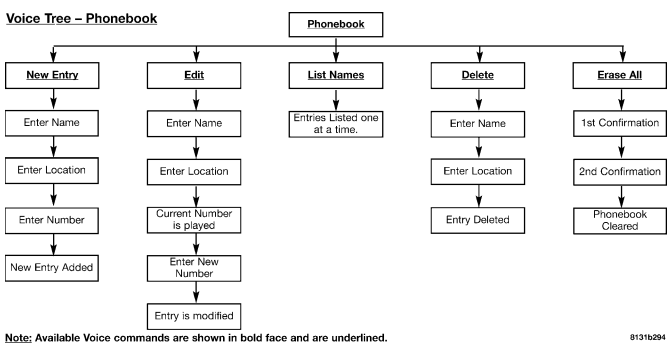
Voice Command Tree
“Voice Tree” at the end of this section.
Help Command
If you need assistance at any prompt, or if you want to know your options are at any prompt, say Help following the voice on beep. The UConnect™ system will play all the options at any prompt if you ask for help. To activate the UConnect™ system from idle, simply press the ’Phone’ button and follow audible prompts for directions. All UConnect™ system sessions begin with a press of the ’Phone’ button on the mirror.
Cancel Command
At any prompt, after the voice on beep, you can say Cancel and you will be returned to the main menu. However, in a few instances the system will take you back to the previous menu.
Pair (Link) UConnect™ System to a Cellular Phone
To begin using your UConnect™ system, you must pair your compatible Bluetooth™ enabled cellular phone.
NOTE: The UConnect™ system use requires a cellular phone equipped with the Bluetooth Hands-Free Profile, version 0.96 or higher. See www.chrysler.com/uconnect for supported phones. To complete the pairing process, you will need to reference your cellular phone owner’s manual. One of the following vehicle specific websites may also provide detailed instructions for pairing with the brand of phone that you have:
NOTE:
The following are general phone to UConnect™ System pairing instructions:
• Press the ’Phone’ button to begin.
• After the Ready prompt and the following beep, say Setup Phone Pairing and follow the audible prompts.
• When prompted, after the voice on beep, say Pair a Phone and follow the audible prompts.
• You will be asked to say a four-digit pin number, which you will later need to enter into your cellular. You can enter any four-digit pin number. You will not need to remember this pin number after the initial pairing process.
• For identification purposes, you will be prompted to give the UConnect™ system a name for your cellular phone. Each cellular phone that is paired should be given a unique phone name.
• You will then be asked to give your cellular phone a priority level between 1 and 7, 1 being the highest priority. You can pair up to seven cellular phones to your UConnect™ system. However, at any given time, only one cellular phone can be in use, connected to your UConnect™ System. The priority allows the UConnect™ system to know which cellular phone to use if multiple cellular phones are in the vehicle at the same time. For example, if priority 3 and priority 5 phones are present in the vehicle, the UConnect™ system will use the priority 3 cellular phone when you make a call. You can select to use a lower priority cellular phone at any time ( Advanced Phone Connectivity).
Call/Dial by Saying a Number
• Press the ’Phone’ button to begin.
• After the Ready prompt and the following beep, say Dial.
• System will prompt you to say the number you want call.
• For example, you can say 234-567-8901.
• The UConnect™ system will confirm the phone number and then dial. The number will appear in the display of certain radios.
Call/Dial by Saying a Name
• Press the “Phone” button to begin.
• After the Ready prompt and the following beep, say “Dial” or Call.
• System will prompt you to say the name of the person you want call.
• After the Ready prompt and the following beep, say the name of the person you want to call. For example, you can say John Doe, where John Doe is a previously stored name entry in the UConnect™ phonebook. Add Names to Your UConnect™ Phonebook, to learn how to store a name in the phonebook.
• The UConnect™ system will confirm the name and then dial the corresponding phone number, which may appear in the display of certain radios.
Add Names to Your UConnect™ Phonebook
NOTE: Adding names to phonebook is recommended when vehicle is not in motion.
• Press the “Phone” button to begin.
• After the Ready prompt and the following beep, say Phonebook New Entry.
• When prompted, say the name of the new entry. Use of long names helps the voice recognition and is recommended. For example, say Robert Smith or Robert instead of Bob.
• When prompted, enter the number designation (e.g., Home, Work, Mobile, or Pager). This will allow you to store multiple numbers for each phonebook entry, if desired.
• When prompted, recite the phone number for the phonebook entry that you are adding.
After you are finished adding an entry into the phonebook, you will be given the opportunity to add more phone numbers to the current entry or to return to the main menu. The UConnect™ system will allow you to enter up to 32 names in the phonebook with each name having up to four associated phone numbers and designations. Each language has a separate 32-name phonebook accessible only in that language.
Edit Entries in the UConnect™ Phonebook
NOTE: Editing phonebook entries is recommended when vehicle is not in motion.
• Press the ’Phone’ button to begin.
• After the Ready prompt and the following beep, say Phonebook Edit.
• You will then be asked for the name of the phonebook entry that you wish to edit.
• Next, choose the number designation (home, work, mobile, or pager) that you wish to edit.
• When prompted, recite the new phone number for the phonebook entry that you are editing.
After you are finished editing an entry in the phonebook, you will be given the opportunities to edit another entry in the phonebook, call the number you just edited, or return to the main menu. Phonebook Edit can be used to add another phone number to a name entry that already exists in the phonebook. For example, the entry John Doe may have a mobile and a home number, but you can add John Doe’s work number later using the Phonebook Edit feature.
Delete Entries in the UConnect™ Phonebook
NOTE: Editing phonebook entries is recommended when vehicle is not in motion.
• Press the ’Phone’ button to begin.
• After the Ready prompt and the following beep, say Phonebook Delete.
• After you enter the Phonebook Delete menu, you will then be asked for the name of the entry that you wish to delete.
You can either say the name of a phonebook entry that you wish to delete or you can say List Names to hear a list of the entries in the phonebook from which you choose. To select one of the entries from the list, press the Voice Recognition button while the UConnect™ system is playing the desired entry and say Delete.
• After you enter the name, the UConnect™ system will ask you which designation you wish to delete, home, work, mobile, or pager. Say the designation you wish to delete.
• Note that only the phonebook entry in the current language is deleted. After confirmation, the phonebook entries will be deleted. Note that only the phonebook in the current language is deleted.
Delete All Entries in the UConnect™ Phonebook
• Press the ’Phone’ button to begin.
• After the Ready prompt and the following beep, say Phonebook Erase All.
• The UConnect™ system will ask you to verify that you wish to delete all the entries from the phonebook.
• After confirmation, the phonebook entries will be deleted.
List All Names in the UConnect™ Phonebook
• Press the ’Phone’ button to begin.
• After the Ready prompt and the following beep, say Phonebook List Names.
• The UConnect™ system will play the names of all the phonebook entries.
• To call one of the names in the list, press the Voice Recognition’ button during the playing of the desired name, and then say Call. NOTE: the user can also exercise Edit or Delete operations at this point.
• The UConnect™ system will then prompt you as to number designation you wish to call.
• The selected number will be dialed.
Phone Call Features
The following features can be accessed through the UConnect™ system if the feature(s) are available on your cellular service plan. For example, if your cellular service plan provides three-way calling, this feature can be accessed through the UConnect™ system. Check with your cellular service provider for the features that you have.
Answer or Reject an Incoming Call – No Call Currently in Progress
When you receive a call on your cellular phone, the UConnect™ system will interrupt the vehicle audio system, if on, and will ask if you would like to answer the call. To reject the call, press and hold the ’Phone’ button until you hear a single beep indicating that the incoming call was rejected.
Answer or Reject an Incoming Call – Call Currently in Progress
If a call is currently in progress and you have another incoming call, you will hear the same network tones for call waiting that you normally hear when using your cell phone. Press the ’Phone’ button to place the current call on hold and answer the incoming call. NOTE: The UConnect™ system compatible phones in market today do not support rejecting an incoming call when another call is in progress. Therefore, the user can only either answer an incoming call or ignore it.
Making a Second Call while Current Call in Progress
To make a second call while you are currently in a call, press the ’Voice Recognition’ button and say Dial or Call followed by the phone number or phonebook entry you wish to call. The first call will be on hold while the second call is in progress. To go back to the first call, Toggling Between Calls. To combine two calls, refer to Conference Call.
Place/Retrieve a Call from Hold
To put a call on hold, press the Phone’ button until you hear a single beep. This indicates that the call is on hold. To bring the call back from hold, press and hold the Phone’ button until you hear a single beep.
Toggling Between Calls
If two calls are in progress (one active and one on hold), press the ’Phone’ button until you hear a single beep indicating that the active and hold status of the two calls have switched. Only one call can be placed on hold at one time.
Conference Call
When two calls are in progress (one active and one on hold), press and hold the ’Phone’ button until you hear a double beep indicating that the two calls have been joined into one conference call.
Three-Way Calling
To initiate three-way calling, press the ’Voice Recognition’ button while a call is in progress and make a second phone call as described under Making a Second Call while Current Call in Progress. After the second call has established, press and hold the ’Phone’ button until you hear a double beep indicating that the two calls have been joined into one conference call.
Call Termination
To end a call in progress, momentarily press the Phone’ button. Only the active call(s) will be terminated and if there is a call on hold, it will become the new active call.
Redial
• Press the ’Phone’ button to begin.
• After the Ready prompt and the following beep, say Redial.
• The UConnect™ system will call the last number that was dialed on your cellular phone. Note: this may not be the last number dialed from the UConnect™ system.
Call Continuation
Call continuation is progression of a phone call on UConnect™ system after the vehicle ignition key has been switched to off. Call continuation functionality available on the vehicle can be any one of three types:
• After ignition key is switched off, a call can continue on the UConnect™ system either until the call ends or until the vehicle battery condition dictates cessation of the call on the UConnect™ system and transfer of the call to the mobile phone.
• After ignition key is switched to off, a call can continue on the UConnect™ system for certain duration, after which the call is automatically transferred from the UConnect™ system to the mobile phone.
• An active call is automatically transferred to the mobile phone after ignition key is switched to off.
UConnect™ System Features
Language Selection
To change the language that the UConnect™ system is using,
• Press the ’Phone’ button to begin.
• After the Ready prompt and the following beep, say the name of the language you wish to switch to (English, Espanol, or Francais, if so equipped).
• Continue to follow the system prompts to complete language selection.
After selecting one of the languages, all prompts and voice commands will be in that language.
NOTE: After every UConnect™ language change operation, only the language specific 32-name phonebook is usable. The paired phone name is not language specific and usable across all languages.
Emergency Assistance
If you are in an emergency and the mobile phone is reachable:
• Pick up the phone and manually dial the emergency number for your area.
If the phone is not reachable and the UConnect™ system is operational, you may reach the emergency number as follows:
• Press the ’Phone’ button to begin.
• After the Ready prompt and the following beep, say Emergency and the UConnect™ system will instruct the paired cellular phone to call the emergency number. This feature is only supported in the USA.
NOTE: The emergency number dialed is based on the Country where the vehicle is purchased (911 for USA and Canada and 060 for Mexico). The number dialed may not be applicable with the available cellular service and area. The UConnect™ system does slightly lower your chances of successfully making a phone call as to that for the cell phone directly. Your phone must be turned on and paired to the UConnect™ system to allow use of this vehicle feature in emergency situations when the cell phone has network coverage and stays paired to the UConnect™ system.
Towing Assistance
If you need towing assistance,
• Press the ’Phone’ button to begin.
• After the Ready prompt and the following beep, say Towing Assistance.
NOTE: The Towing Assistance number dialed is based on the Country where the vehicle is purchased (1-800- 528-2069 for USA, 1-877-213-4525 for Canada, 55-14-3454 for Mexico city and 1-800-712-3040 for outside Mexico city in Mexico).
Please refer to the 24-Hour “Towing Assistance” coverage details in the Warranty information booklet and on the 24–Hour Towing Assistance Card.
Paging
To learn how to page, Working with Automated Systems. Paging works properly except for pagers of certain companies which time-out a little too soon to work properly with the UConnect™ system.
Voice Mail Calling
To learn how to access your voice mail, Working with Automated Systems.
Working with Automated Systems
This method is designed to be used in instances where one generally has to press numbers on the cellular phone keypad while navigating through an automated telephone system. You can use your UConnect™ system to access a voicemail system or an automated service, such as, paging service or automated customer service. Some services require immediate response selection, in some instances, that may be too quick for use of UConnect™ system. When calling a number with your UConnect™ system that normally requires you to enter in a touch-tone sequence on your cellular phone keypad, you can push the ’Voice Recognition’ button and say the sequence you wish to enter followed by the word Send. For example, if required to enter your pin number followed with a pound 3 7 4 6 #, you can press the ’Voice Recognition’ button and say 3746# Send. Saying a number, or sequence of numbers, followed by Send is also to be used to navigate through an automated customer service center menu structure and to leave a number on a pager.
Barge In – Overriding Prompts
The ’Voice Recognition’ button can be used when you wish to skip part of a prompt and issue your voice recognition command immediately. For example, if a prompt is playing Would you like to pair a phone, clear a, you could press the ’Voice Recognition’ button and say Pair a Phone to select that option without having to listen to the rest of the voice prompt.
Turning Confirmation Prompts On/Off
Turning confirmation prompts off will stop the system from confirming your choices (e.g., the UConnect™ system will not repeat a phone number before you dial it).
• Press the ’Phone’ button to begin.
• After the Ready prompt and the following beep, say Setup Confirmations. The UConnect™ system will play the current confirmation prompt status and you will be given the choice to change it.
Phone and Network Status Indicators
If available on the radio and/or on a premium display such as the instrument panel cluster, and supported by your cell phone, the UConnect™ system will provide notification to inform you of your phone and network status when you are attempting to make a phone call using UConnect™. The status is given for roaming network signal strength, phone battery strength, etc.
Dialing Using the Cellular Phone Keypad
You can dial a phone number with your cellular phone keypad and still use the UConnect™ system (while dialing via the cell phone keypad, the user must exercise caution and take precautionary safety measures). By dialing a number with your paired Bluetooth™ cellular phone, the audio will be played through your vehicle’s audio system. The UConnect™ system will work the same as if you dial the number using voice recognition.
NOTE: Certain brands of mobile phones do not send the dial ring to the UConnect™ system to play it on the vehicle audio system, so you will not hear it. Under this situation, after successfully dialing a number, the user may feel that the call did not go through even though the call is in progress. Once your call is answered, you will hear the audio.
Mute/Un-mute (Mute off)
When you mute the UConnect™ system, you will still be able to hear the conversation coming from the other party, but the other party will not be able to hear you. In order to mute the UConnect™ system:
• Press the ’Voice Recognition’ button.
• After the Ready prompt and the following beep, say Mute.
In order to un-mute the UConnect™ system:
• Press the ’Voice Recognition’ button.
• After the Ready prompt and the following beep, say Mute-off.
Information Service
When using AT&T Wireless Service, dialing to phone number #121, you can access voice activated automated system to receive news, weather, stocks, traffic, etc. related information.
Advanced Phone Connectivity
Transfer Call to and from Cellular Phone
The UConnect™ system allows on going calls to be transferred from your cellular phone to the UConnect™ system without terminating the call. To transfer an ongoing call from your UConnect™ paired cellular phone to the UConnect™ system or vice-versa, press the ’Voice Recognition’ button and say Transfer Call.
Connect or Disconnect Link Between the UConnect™ System and Cellular Phone
Your cellular phone can be paired with many different electronic devices, but can only be actively connected with one electronic device at a time. If you would like to connect or disconnect the Bluetooth™ connection between a UConnect™ paired cellular phone and the UConnect™ system, then follow the instruction described in your cellular phone user’s manual.
List Paired Cellular Phone Names
• Press the ’Phone’ button to begin.
• After the “Ready” prompt and the following beep, say “Setup Phone pairing”.
• When prompted, say List Phones.
• The UConnect™ system will play the phone names of all paired cellular phones in order from the highest to the lowest priority. To “select” or “delete” a paired phone being announced, press the Voice recognition’
button and say “Select” or “Delete.” Also, see the next two sections for an alternate way to “select” or “delete” a paired phone.
Select another Cellular Phone
This feature allows you to select and start using another phone with the UConnect™ system. The phone must have been previously paired to the UConnect™ system that you want to use it with.
• Press the ’Phone’ button to begin.
• After the Ready prompt and the following beep, say Setup Select Phone and follow the prompts.
• You can also press the Voice Recognition’ button anytime while the list is being played, and then choose the phone that you wish to select.
• The selected phone will be used for the next phone call. If the selected phone is not available, the UConnect™ system will return to using the highest priority phone present in or near (approximately with in 30 feet) the vehicle. Delete UConnect™ Paired Cellular Phones
• Press the ’Phone’ button to begin.
• After the Ready prompt and the following beep, say Setup Phone Pairing.
• At the next prompt, say Delete and follow the prompts.
• You can also press the Voice Recognition’ button anytime while the list is being played and then choose the phone you wish to delete.
Things You Should Know About Your UConnect™ System
Voice Recognition (VR)
• Always wait for the beep before speaking.
• Speak normally, without pausing, just as you would speak to a person sitting approximately eight (8) feet away from you.
• Make sure that no one other than you is speaking during a voice recognition period.
• Performance is maximized under:
• low-to-medium blower setting,
• low-to-medium vehicle speed,
• low road noise,
• smooth road surface,
• fully closed windows,
• dry weather condition.
• Even though the system is designed for users speaking in North American English, French, and Spanish accents, the system may not always work for some.
• When navigating through an automated system, such as voice mail, or when sending a page at the end of speaking the digit string, make sure to say send.
• Storing names in phonebook when vehicle is not in motion is recommended.
• It is not recommended to store similar sounding names in the UConnect™ phonebook.
• UConnect™ phonebook nametag recognition rate is optimized for the voice of the person who stored the name in the phonebook.
• You can say O (letter O) for 0 (zero). 800 must be spoken eight-zero-zero.
• Even though international dialing for most number combinations is supported, some shortcut dialing number combinations may not be supported.
Far End Audio Performance
• Audio quality is maximized under:
• low-to-medium blower setting,
• low-to-medium vehicle speed,
• low road noise,
• smooth road surface,
• fully closed windows, and
• dry weather condition.
• Operation from driver seat.
• Performance, such as audio clarity, echo, and loudness to a large degree rely on the phone and network, and not the UConnect™ system.
• Echo at far end can sometime be reduced by lowering the in-vehicle audio volume.
Bluetooth Communication Link
Occasionally, Cellular phones have been found to lose connection to the UConnect™ system. When this happens, the connection can generally be re-established by switching the phone off/on. Your cell phone is recommended to remain in Bluetooth on mode.
Power-Up
After switching the ignition key from OFF to either ON or ACC position, or after a reset, you must wait at least five (5) seconds prior to using the system.


SEATS
Power Seats
The power seat switch is on the outboard side of the seat near the floor. Use this switch to move the driver’s seat up or down, forward or rearward, or to tilt the seat. The passenger’s seat will move up or down, forward or rearward.
WARNING! Adjusting a seat while the vehicle is moving is dangerous. The sudden movement of the seat could cause you to lose control. The seat belt might not be properly adjusted and you could be injured. Adjust the seat only while the vehicle is parked.
CAUTION! Do not place any article under a power seat as it may cause damage to the seat controls.
Power Reclining Seats
The recliner control is located on the outboard side of the seat.

WARNING! Do not ride with the seatback reclined so that the shoulder belt is no longer resting against your chest. In a collision you could slide under the seat belt and be seriously or even fatally injured. Use the recliner only when the vehicle is parked.
Lumbar Support
This feature allows you to increase or decrease the amount of lumbar support. Turn the control lever forward to increase and rearward to decrease the desired amount of lumbar support.

Head Restraints
Head restraints can reduce the risk of whiplash injury in the event of impact from the rear. Adjustable restraints should be adjusted so that the upper edge is as high as practical. The head restraints have a locking button, which must be pushed in to lower the head restraint. The restraints may be raised without pushing in the button.

Heated Seats — If Equipped
Heated seats, which are available only with leather upholstery, provide comfort and warmth on cold days and can help soothe sore muscles and backs. The heaters provide the same heat level for both cushion and back. The controls for the driver and front passenger heated seats are located near the bottom center of the instrument panel.

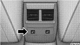
On vehicles equipped with rear heated seats, the seats closest to the doors are heated. The controls for these seats are located on the rear of the center console.
After turning on the ignition, you and your passenger(s) can choose from High, Off, or Low heat settings. Amber LEDs in the switch indicate the level of heat in use. Two LEDs will illuminate for high, one for low, and none for off.
Press the switch once to select high-level heating. Press the switch a second time to select low-level heating. Press the switch a third time to shut off the heating elements. If high-level heating is selected, the system will automatically switch to low level after 30 minutes of continuous operation. At that time, the number of illuminated LEDs changes from two to one, indicating the change. Operation on the low setting also turns off automatically after 30 minutes.
NOTE: Once a heat setting is selected, heat will be felt within two to five minutes.
WARNING! Persons who are unable to feel pain to the skin because of advanced age, chronic illness, diabetes, spinal cord injury, medication, alcohol use, exhaustion or other physical condition must exercise care when using the seat heater. It may cause burns even at low temperatures, especially if used for long periods. Do not place anything on the seat that insulates against heat, such as a blanket or cushion. This may cause the seat heater to overheat.
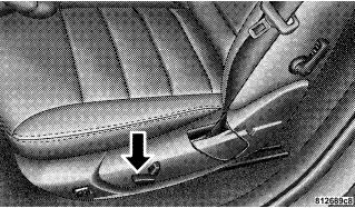
Folding Rear Seat

The rear seatbacks can be folded forward to provide an additional storage area. Pull on the loops shown in the illustration to fold down either or both seatbacks. These loops can be tucked away when not in use. When the seatback is folded to the upright position, make sure it is latched by strongly pulling on the top of the seatback above the seat strap.
WARNING!
• Be certain that the seatback is securely locked into position. If the seatback in not securely locked into position the seat will not provide the proper stability for child seats and/or passengers. An improperly latched seat could cause serious injury.
• The cargo area in the rear of the vehicle (with the rear seatbacks in the locked-up or folded down position) should not be used as a play area by children when the vehicle is in motion. They could be seriously injured in an accident. Children should be seated and using the proper restraint system.
DRIVER MEMORY SEAT — IF EQUIPPED
This feature allows the driver to store up to two different memory profiles, for easy recall through a memory switch. Each memory profile contains desired position settings for the driver seat, side mirror, adjustable pedals (if equipped), and power tilt and telescopic steering column (if equipped), and a set of desired radio station presets. The memory switch is located on the driver’s door panel. The switch contains an (S) button to activate the memory save function. It also contains a rocker switch labeled with the number (1) and the number (2). The rocker switch allows the driver to recall either of two preprogrammed memory profiles by pressing the appropriate side of the switch.
Programming The Memory Feature
To create a new memory profile, perform the following:
NOTE: Saving a new memory profile will erase an existing profile from memory.
1. Adjust all memory profile settings to desired preferences (i.e. seat, side mirror, adjustable pedals [if equipped], power tilt and telescopic steering column [if equipped], and radio station presets).
2. Press and release the Set (S) button on the memory switch, then press the side of the rocker switch labeled (1) within 5 seconds. The Electronic Vehicle Information Center (EVIC) — if equipped will display which memory position is being set. If desired, a second memory profile can be stored into memory as follows:
1. Adjust all memory profile settings to desired preferences (i.e. seat, side mirror, adjustable pedals [if equipped], power tilt and telescopic steering column [if equipped], and radio station presets).
2. Press and release the Set (S) button on the memory switch, then press the side of the rocker switch labeled (2) within 5 seconds. The Electronic Vehicle Information Center (EVIC) — if equipped will display which memory position is being set.
NOTE: Memory profiles can be set without the vehicle in Park, but the vehicle must be in Park to recall a memory profile.
NOTE: The Recall Memory with Remote Key Unlock feature can be enabled through the Electronic Vehicle Information Center (EVIC) — if equipped. For details, “Personal Settings (Customer Programmable Features)” under “Electronic Vehicle Information Center (EVIC)” in Section 4 of this manual.
Linking & Unlinking the Remote Keyless Transmitter to the Memory Feature
Your Remote Keyless Entry Transmitters can be programmed to recall one of two pre-programmed memory profiles by pressing the UNLOCK button on the Remote Keyless Entry Transmitter.
To program your transmitters, perform the following:
1. Remove key from ignition.
2. Select desired memory profile 1 or 2.
3. Press and release the Set (S) button on the memory switch, then press and release the side of the rocker switch labeled 1 or 2 accordingly. Memory Profile Set” (1 or 2) will display in the instrument cluster on vehicles equipped with the Electronic Vehicle Information Center (EVIC).
4. Press and release the LOCK button on the transmitter within 10 seconds.
NOTE: Your transmitters can be unlinked to your memory settings by pressing the Set (S) button followed by the UNLOCK button on the transmitter in Step 4 above.
Memory Position Recall
NOTE: The vehicle must be in Park to recall memory positions. If a recall is attempted when the vehicle is not in Park, a message will display in the Electronic Vehicle Information Center (EVIC) — if equipped.
To recall the memory settings for driver one, press memory button number 1 on the driver’s door or the “Unlock” button on the Remote Keyless Entry transmitter linked to memory position 1.
To recall the memory setting for driver two, press memory button number 2 on the driver’s door or the “Unlock” button on the Remote Keyless Entry transmitter linked to memory position 2.
A recall can be cancelled by pressing any of the memory buttons (S, 1, or 2) on the drivers door during a recall. When a recall is cancelled, the driver seat, side mirror, adjustable pedals (if equipped), and power tilt and telescopic steering column (if equipped) stop moving. A delay of one second will occur before another recall can be selected.
Easy Entry/Exit Seat (Available with Memory Seat Only)
This feature provides automatic driver seat positioning to enhance driver mobility when entering and exiting the vehicle.
The distance the driver seat moves depends on where you have the driver seat positioned when you remove the key from the ignition switch.
• When you remove the key from the ignition switch, the driver seat will move about 2.4 inches (60 mm) rearward if the driver seat position is greater than or equal to 3.5 inches (90 mm) forward of the rear stop. The seat will return to its previously set position when you insert the key into the ignition switch and turn it out of the LOCK position.
• When you remove the key from the ignition switch, the driver seat will move to a position 1.2 inches (30 mm) forward of the rear stop if the driver seat position is between 2.4 inches and 3.5 inches (60 mm and 90 mm) forward of the rear stop. The seat will return to its previously set position when you insert the key into the ignition switch and turn it out of the LOCK position.
• The Easy Entry/Easy Exit feature is disabled when the driver seat position is less than 2.4 inches (60 mm) forward of the rear stop. At this position, there is no benefit to the driver by moving the seat for Easy Exit or Easy Entry.
Each stored memory setting will have an associated Easy Entry and Easy Exit position.
NOTE: The Easy Entry/Easy Exit feature can be enabled or disabled through the programmable features in the Electronic Vehicle Information Center (EVIC). For details, “Automatically Move Seat Back on Exit,” under “Personal Settings (Customer Programmable Features),” under “Electronic Vehicle Information Center (EVIC)” in Section 4 of this manual.
TO OPEN AND CLOSE THE HOOD
Two latches must be released to open the hood. First, pull the hood release lever located under the left side of the instrument panel.

Next, move to the outside of the vehicle and push the safety catch to the left. The safety catch is located under the center front edge of the hood.

Use the hood prop rod (if equipped) to secure the hood in the open position. To prevent possible damage, do not slam the hood to close it. Lower the hood, until it is open approximately 6 inches (15 cm), and then drop it. This should secure both latches. Never drive your vehicle unless the hood is fully closed, with both latches engaged.
WARNING! If the hood is not fully latched, it could fly up when the vehicle is moving and block your forward vision. You could have a collision. Be sure all hood latches are fully latched before driving.
LIGHTS
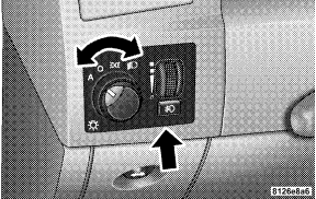
Headlight Switch


Rotate the headlight switch clockwise to the first detent for parking light and instrument panel light operation. Turn it to the second detent for headlight, parking light, and instrument panel light operation.
Automatic Headlights – If Equipped
This system automatically turns the headlights ON or OFF according to ambient light levels. To turn the system ON, rotate the headlight switch counter-clockwise to the AUTO (A) position. When the system is ON, the Headlight Time Delay feature is also ON. This means the headlights will stay ON for up to 90 seconds after you turn the ignition switch OFF. To turn the Automatic System OFF, move the headlight switch out of the AUTO (A) position.
NOTE: The engine must be running before the headlights will come ON in the Automatic mode.
Headlights On with Wipers (Available with Auto Headlights Only)
When this feature is active, the headlights will turn on approximately 10 seconds after the wipers are turned on if the headlight switch is placed in the AUTO position. In addition, the headlights will turn off when the wipers are turned off if they were turned on by this feature. The Headlights On with Wipers feature can be turned on or off through the Electronic Vehicle Information Center (EVIC) — if equipped. For details, ”Headlights On with Wipers,” under “Personal Settings (Customer Programmable Features),” under “Electronic Vehicle Information Center” in Section 4 of this manual.
SmartBeams — If Equipped
The SmartBeam system provides increased forward lighting at night by automating high beam control through the use of a digital camera mounted on the inside rearview mirror. This camera detects vehicle specific light and automatically switches from high beams to low beams until the approaching vehicle is out of view.
To Activate:
1. Select “Automatic High Beams — ON” through the Electronic Vehicle Information Center (EVIC). For details, “Personal Settings (Customer Programmable Features),” under “Electronic Vehicle Information Center” in Section 4 of this manual.
2. Rotate the headlight switch counter-clockwise to the AUTO (A) position.
3. Push the Multi-Function Lever away from you to switch the headlights to the HIGH BEAM position.
NOTE: This system will not activate until the vehicle is at or above 25 mph (40 km/h).
To Deactivate:
Perform either of the following steps to deactivate the SmartBeam system.
1. Pull the Multi-Function Lever toward you to switch the headlights from the HIGH BEAM to the LOW BEAM position.
2. Rotate the headlight switch clockwise from the AUTO (A) to the ON position.
NOTE: Broken, muddy, or obstructed headlights and taillights of vehicles in the field of view will cause headlights to remain on longer (closer to the vehicle). Also, dirt, film, and other obstructions on the windshield or camera lens will cause the system to function improperly
Headlight Time Delay
This feature provides the safety of headlight illumination for 90 seconds (programmable) when leaving your vehicle in an unlighted area.
To activate the delay feature, turn off the ignition switch while the headlights are still on. Then, turn off the headlights within 45 seconds. The delay interval begins when headlight switch is turned off.
If you turn the headlights, park lights, or ignition switch on again, the system will cancel the delay.
If you turn the headlights off before the ignition, they will turn off in the normal manner.
NOTE: The lights must be turned off within 45 seconds of turning the ignition off to activate this feature
The Headlight delay time is programmable on vehicles equipped with the Electronic Vehicle Information Center (EVIC). For details, “Delay Turning Headlights Off,” under “Personal Settings (Customer Programmable Features),” under “Electronic Vehicle Information Center (EVIC)” in Section 4 of this manual.
Daytime Running Lights (Canada Only)
Daytime Running Lights (Canada Only) The high beam headlights will come on as Daytime Running Lights, whenever the ignition switch is on, the headlights are off, and the parking brake is off. The headlight switch must be used for normal nighttime driving.
Lights-on Reminder
If the headlights or parking lights are on after the ignition is turned OFF, a chime will sound to alert the driver when the driver’s door is opened.
Fog Lights — If Equipped

low beam headlights and press the fog light switch.
An indicator light in the instrument cluster illuminates when the fog lights are turned on.
NOTE: The fog lights will operate with the low beam headlights or parking lights on. However, selecting the high beam headlights will turn off the fog lights.
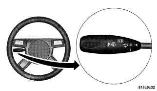
Multi-Function Lever
The multi-function lever controls the operation of the turn signals, headlight beam selection, and passing lights. The lever is located on the left side of the steering column.
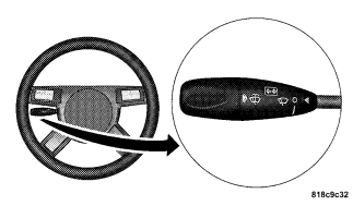
Turn Signals
Move the Multi-Function Lever up or down and the corresponding turn signal indicator in the instrument cluster flashes to show proper operation of the front and rear turn signal lights. Moving the Multi-Function Lever up or down also causes the corresponding turn signal indicator in the outside mirror (if so equipped) to flash. For details, “Outside Mirrors with Turn Signal & Approach Lighting” under “Mirrors” in this section. You can also signal a lane change by moving the lever partially up or down without moving beyond the detent. Releasing the lever at the detent will provide 3 flashes. If either light has a very fast flash rate, check for a defective outside light bulb. If an indicator fails to light when the lever is moved, it would suggest that the fuse or indicator is defective or there may be a circuit failure.
NOTE: A “Turn Signal On” message will appear in the Electronic Vehicle Information Center (EVIC) — if equipped and a continuous chime will sound if the vehicle is driven more than 1 mile (1.6 km) with either turn signal on.
Highbeam/Lowbeam Select
Switch Push the Multi-Function Lever away from you to switch the headlights to HIGH beam. Pull the Lever towards you to switch the headlights back to LOW beam.
Flash to Pass
You can signal another vehicle with your headlights by lightly pulling the Multi-Function Lever toward you. This will cause the headlights to turn on at high beam and remain on until the lever is released.
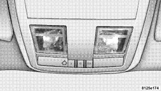
Overhead Console Map/Reading Lights
These lights are mounted between the sun visors on the overhead console. Each light is turned ON by pressing the lens. Press the lens a second time to turn OFF the light. These lights also turn on when a door is opened, or when the unlock button on the remote keyless entry transmitter is pressed, or when the dimmer control is turned fully upward, past the second detent.
Interior Lights
The interior lights come on when a door is opened. To protect the battery, the interior lights will turn off automatically 10 minutes after the ignition switch is moved to the LOCK position. This will occur if the interior lights were switched on manually or are on because a door is open. This includes the glove box light, but not the trunk light. To restore interior light operation, either turn the ignition switch ON or cycle the light switch.
Dimmer Control

rotating the dimmer control upward will increase the brightness of the instrument panel lights.
Dome Light Position
Rotate the dimmer control completely upward to the second detent to turn on the interior lights. The interior lights will remain on when the dimmer control is in this position.
Interior light Defeat (OFF)
Rotate the dimmer control to the extreme bottom “OFF” position. The interior lights will remain off when the doors are open.
Parade Mode (Daytime Brightness Feature)
Rotate the dimmer control upward to the first detent. This feature brightens all text displays such as the odometer, Electronic Vehicle Information Center (EVIC) — if equipped, and radio when the parking lights or headlights are on.
WINDSHIELD WIPERS AND WASHERS

side of the steering column.
Rotate the end of the multi-function lever to the first detent past the intermittent settings for Low-speed wiper operation, or to the second detent past the intermittent settings for High-speed wiper operation.
CAUTION! Turn the windshield wipers off when driving through an automatic car wash. Damage to the windshield wipers may result if the wiper switch is left in any position other than OFF.
Intermittent Wiper System
Use the intermittent wiper when weather conditions make a single wiping cycle with a variable pause between cycles desirable. Rotate the end of the multifunction lever to the first detent position, and then turn the end of the lever to select the desired delay interval. There are six delay settings, which allow you to regulate the wipe interval from a minimum of one cycle every second to a maximum of approximately 23 seconds between cycles.
WARNING! Sudden loss of visibility through the windshield could lead to an accident. You might not see other vehicles or other obstacles. To avoid sudden icing of the windshield during freezing weather, warm the windshield with defroster before and during windshield washer use.
Mist Feature
Push the multi-function lever inward (toward the steering column) to the first detent to activate a single wipe cycle to clear off road mist or spray from a passing vehicle. The wipers will continue to operate until you release the lever.
Windshield Washers
To use the washer, push the multi-function lever inward (toward the steering column) to the second detent and hold it for as long as washer spray is desired. If you activate the washer while the windshield wiper control is in the delay range, the wipers will operate for two wipe cycles after releasing the lever and then resume the intermittent interval previously selected. If you activate the washer while the windshield wiper is turned OFF, the wipers will operate for two wipe cycles and then turn OFF.
Headlights On with Wipers (Available with Auto Headlights Only)
When this feature is active, the headlights will turn on approximately 10 seconds after the wipers are turned on if the headlight switch is placed in the AUTO position. In addition, the headlights will turn off when the wipers are turned off if they were turned on by this feature. The Headlights On with Wipers feature can be turned on or off through the Electronic Vehicle Information Center (EVIC) — if equipped. For details, ”Headlights On with Wipers,” under “Personal Settings (Customer Programmable Features),” under “Electronic Vehicle Information Center” in Section 4 of this manual.
Rain Sensing Wipers — If Equipped
This feature senses moisture on the windshield and automatically activates the wipers for the driver. This feature is especially useful for road splash or over spray from the windshield washers of the vehicle ahead. Rotate the end of the multi-function lever to one of the six intermittent wiper settings to activate this feature. The sensitivity of the system is adjustable from the multi-function lever. Wiper delay position 1 is the least sensitive and wiper delay position 6 is the most sensitive. Choose setting 3 or 4 for normal rain conditions. Choose setting 2 or 1 if you desire less wiper sensitivity. Choose setting 5 or 6 if you desire more sensitivity. Place the lever in the OFF position when not using the system.
NOTE:
• The rain-sensing feature will not operate when the wiper speed is in the LOW or HIGH position.
• The rain-sensing feature may not function properly when ice or dried salt water is present on the windshield.
• Use of Rain-X or products containing wax or silicone may reduce rain sensor performance.
• The Rain Sense feature can be turned on and off through the Electronic Vehicle Information Center (EVIC) — if equipped. For details, “Personal Settings (Customer Programmable Features)” under “Electronic Vehicle Information Center (EVIC)” in Section 4 of this manual.
The rain sensing system has protective features for the wiper blades and arms. It will not operate under the following conditions:
• Low Temperature Wipe Inhibit — The rain-sensing feature will not operate when the ignition is first switched ON, and the vehicle is stationary, and the outside temperature is below 32° F (0° C), unless the wiper control on the multi-function lever is moved, or the vehicle speed becomes greater than 0 mph (0 km/h), or the outside temperature rises above freezing.
• Neutral Wipe Inhibit — The rain-sensing feature will not operate when the ignition is ON, and the transmission shift lever is in the N (Neutral) position, and the vehicle speed is less than 5 mph (8 km/h), unless the wiper control on the multi-function lever is moved or the shift lever is moved out of the N (Neutral) position.
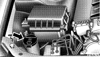
Adding Washer Fluid
The windshield washer fluid reservoir is located in the front of the engine compartment on the passenger side of the vehicle. Be sure to check the fluid level in the reservoir at regular intervals. Fill the reservoir with windshield washer solvent (not radiator antifreeze) and operate the system for a few seconds to flush out the residual water.
The fluid reservoir will hold nearly 1 gallon (4 liters) of washer fluid when the message “Low Washer Fluid” appears in the Electronic Vehicle Information Center (EVIC) — if equipped.
WARNING! Commercially available windshield washer solvents are flammable. They could ignite and burn you. Care must be exercised when filling or working around the washer solution.
HEADLIGHT WASHERS — IF EQUIPPED
The multi-function lever operates the headlight washers when the ignition switch is in the ON position and the headlights are ON. The multi-function lever is located on the left side of the steering column. To use the headlight washers, push the multi-function lever inward (toward the steering column) to the second detent and release it. The headlight washers will spray a timed high-pressure spray of washer fluid onto each headlight lens. In addition, the windshield washers will spray the windshield and the windshield wipers will cycle.
NOTE: The headlight washers will operate on the first spray of the windshield washer and then every fourth spray after that.
Adding Washer Fluid
The headlight washer and windshield washer share the same fluid reservoir. The reservoir is located in the front of the engine compartment on the passenger side of the vehicle. Be sure to check the fluid level in the reservoir at regular intervals. Fill the reservoir with windshield washer solvent (not radiator antifreeze) and operate the system for a few seconds to flush out the residual water.

WARNING! Commercially available windshield washer solvents are flammable. They could ignite and burn you. Care must be exercised when filling or working around the washer solution.
TILT/TELESCOPING STEERING COLUMN
This feature allows you to tilt the steering column upward or downward. It also allows you to lengthen or shorten the steering column. The tilt/telescoping control handle is located below the steering wheel at the end of the steering column.

To unlock the steering column, pull the control handle outward. To tilt the steering column, move the steering wheel upward or downward as desired. To lengthen or shorten the steering column, pull the steering wheel outward or push it inward as desired. To lock the steering column in position, push the control handle inward until fully engaged.
WARNING! Do not adjust the steering wheel while driving. The telescoping adjustment must be locked while driving. Adjusting the steering wheel while driving or driving without the telescoping adjustment locked could cause the driver to lose control of the vehicle.
POWER TILT/TELESCOPING STEERING COLUMN — IF EQUIPPED
This feature allows you to tilt the steering column upward or downward. It also allows you to lengthen or shorten the steering column. The power tilt/telescoping steering column lever is located below the multi-function lever on the steering column.
To tilt the steering column, move the lever up or down as desired. To lengthen or shorten the steering column, pull the lever toward you or push the lever away from you as desired.
NOTE: For vehicles equipped with Driver Memory Seat, you can use your remote keyless entry transmitter or the memory switch on the driver’s door panel to return the tilt/telescopic steering column to preprogrammed positions. “Driver Memory Seat” in this section for details.
WARNING! Moving the steering column while the vehicle is moving is dangerous. Without a stable steering column, you could lose control of the vehicle and have an accident. Adjust the column only while the vehicle is stopped.
ADJUSTABLE PEDALS — IF EQUIPPED
The adjustable pedals system is designed to allow a greater range of driver comfort for steering wheel tilt and seat position. This feature allows both the brake and accelerator pedal to move toward or away from the driver to provide improved position with the steering wheel. The switch is located on the front side of the driver’s seat cushion side shield.
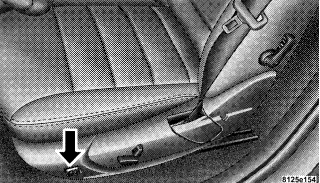
Press the switch forward to move the pedals forward (toward the front of the vehicle).
Press the switch rearward to move the pedals rearward (toward the driver).
• The pedals can be adjusted with the ignition OFF.
• The pedals can be adjusted while driving.
• The pedals cannot be adjusted when the vehicle is in R (Reverse) or when the Speed Control is ON. One of the following messages will display in the Electronic Vehicle Information Center (EVIC) — if equipped if a pedal adjustment is attempted when the system is locked out: “Adjustable Pedal Disabled — Cruise Control Engaged” or “Adjustable Pedal Disabled — Vehicle In Reverse.”
NOTE: For vehicles equipped with Driver Memory Seat, you can use your remote keyless entry transmitter or the memory switch on the driver’s door panel to return the adjustable pedals to pre-programmed positions. “Driver Memory Seat” in this section for details.
CAUTION! Do not place any article under the adjustable pedals or impede its ability to move as it may cause damage to the pedal controls. Pedal travel may become limited if movement is stopped by an obstruction in the adjustable pedal’s path.
ELECTRONIC SPEED CONTROL
When engaged, this device takes over the accelerator operation at speeds greater than 25 mph (40 km/h).
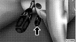
Electronic Speed Control Operation
The speed control lever (located on the left side of the steering column) operates the system.

To Activate:

instrument cluster on some models) will illuminate to show that the speed control system is ON. To turn the system OFF, push the lever inward (toward the steering column) again and release. At this time, the system and the indicator light will turn off.
WARNING! Leaving the Electronic Speed Control system on when not in use is dangerous. You could accidentally set the system or cause it to go faster than you want. You could lose control and have an accident. Always leave the system OFF when you aren’t using it.
To Set At A Desired Speed:
When the vehicle reaches the speed desired, push the lever down and release (“SET/DECEL”). Remove your foot from the accelerator pedal and the vehicle will operate at the selected speed.
NOTE:
• Speed control will only function in third, fourth, or fifth gear when in the Autostick Mode (if equipped).
• The speed control may not engage if a different size tire is installed on one wheel, such as the compact spare tire.
To Deactivate:
The system will disable Electronic Speed Control without erasing the memory if you:
• Softly tap the brake pedal.
• Depress the brake pedal.
• Push the speed control lever away from you (“CANCEL”). Pushing and releasing the lever (“ON/OFF”) or turning off the ignition erases the set speed from memory.
To Resume Speed:
If you deactivated the speed control without erasing the set speed from memory and your vehicle speed is above 20 mph (32 km/h) you can resume the previous set speed. To do so, push the lever up and release (RES/ ACCEL), and then remove your foot from the accelerator pedal.
To Vary the Speed Setting:
When the speed control is set, you can increase speed by pushing the lever up and holding (“RES/ACCEL”). When the lever is released, a new set speed will be established. Pushing the lever up and releasing (“RES/ACCEL”) once will result in a 1 mph (1.6 km/h) speed increase. Each time the lever is pushed up and released, speed increases so that pushing the lever up and releasing three times will increase speed by 3 mph (4.8 km/h), etc. To decrease speed while speed control is set, push the lever down and hold (“SET/DECEL”). Release the lever when the desired speed is reached, and a new set speed will be established. Pushing down and releasing the lever (“SET/DECEL”) once will result in a 1 mph (1.6 km/h) speed decrease. Each time the lever is pushed down and released, speed decreases.
To Accelerate For Passing:
Depress the accelerator as you would normally. When the pedal is released, the vehicle will return to the set speed.
NOTE: The speed control system maintains speed up and down hills. A slight speed change on moderate hills is normal. Four speed automatic transmissions will experience a downshift to 3rd gear while climbing uphill or descending downhill. This downshift to 3rd gear is necessary to maintain vehicle set speed. On steep hills, a greater speed loss or gain may occur so it may be preferable to drive without speed control.
WARNING! Speed Control can be dangerous where the system can’t maintain a constant speed. Your vehicle could go too fast for the conditions, and you could lose control. An accident could be the result. Don’t use Speed Control in heavy traffic or on roads that are winding, icy, snow-covered, or slippery.
ADAPTIVE CRUISE CONTROL (ACC) — IF EQUIPPED
Adaptive Cruise Control (ACC) increases the driving convenience provided by cruise control while traveling on highways and major roadways. However, it is not a safety system and not designed to prevent collisions. ACC will allow you to keep cruise control engaged in light to moderate traffic conditions without the constant need to reset your cruise control. ACC utilizes an infrared sensor designed to detect a vehicle directly ahead in your path within a distance of 328 ft (100 m).
NOTE:
• If the sensor does not detect a vehicle directly ahead of you, ACC will function in the same way as standard cruise control system. For additional information, “Electronic Speed Control” in this section.
• If the ACC sensor detects a vehicle ahead, ACC will apply limited braking or acceleration automatically so that your vehicle maintains a preset following distance.
WARNING!
• Adaptive Cruise Control (ACC) is a convenience system. It is not a substitute for active driving involvement. It is always the driver’s responsibility to be attentive of road, traffic, and weather conditions, vehicle speed, distance to the vehicle ahead, and most importantly brake operation to ensure safe operation of the vehicle under all road conditions. Your complete attention is always required while driving to maintain safe control of your vehicle. Failure to follow these warnings can result in an accident or serious personal injury.
• The ACC system:
− Does not react to pedestrians, oncoming vehicles, and stationary objects (i.e. a stopped vehicle in a traffic jam or a disabled vehicle).
− Does not predict the lane curvature or the movement of preceding vehicles and will not compensate for such changes. − Cannot take street, traffic, and weather conditions into account, and may be limited upon adverse sight distance conditions.
− Does not always fully recognize complex driving conditions, which can result in wrong or missing distance warnings.
− May not detect a vehicle ahead when strong light (for example, sunrise or sunset) is directly shining on the front of the vehicle.
− Can only apply a maximum of 25% of the vehicle’s braking capability, and will not bring the vehicle to a complete stop.
WARNING!
You should switch off the ACC system:
• When driving in fog; heavy rain; heavy snow; sleet; heavy traffic; and complex driving situations (i.e. in highway construction zones).
• When entering a turn lane or highway off ramp; when driving on roads that are winding, icy, snow-covered, slippery, or have steep uphill or downhill slopes; and when towing a trailer.
• When circumstances do not allow safe driving at a constant speed. Failure to follow these warnings can result in an accident or serious personal injury.
Adaptive Cruise Control (ACC) Operation
The speed control lever (located on the left side of the steering column) operates the ACC system.

Activating Adaptive Cruise Control (ACC)
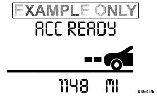
You can only activate ACC if the vehicle speed is between 25 mph and 100 mph (Canada 30 km/h and 180 km/h). When the system is turned on and in the READY state, the Electronic Vehicle Information Center (EVIC) displays “ACC READY.” When the system is OFF, the EVIC displays “ACC OFF.”
NOTE: You cannot enable ACC under the following conditions:
• When you apply the brakes. • When the parking brake is set.
• When the automatic transmission is in P (Park), R (Reverse), or N (Neutral).
• When the Electronic Stability Program (ESP) is switched off.
• When pressing the RES/ACCEL switch without a previously set speed in memory.
To Activate:
Push the speed control lever inward (toward the steering column) and release (“ON/OFF”). The ACC menu in the EVIC displays “ACC READY.”

To turn the system OFF, push the lever inward (toward the steering column) again and release. At this time, the system will turn off and the EVIC will display “ACC OFF.”
WARNING! Leaving the Adaptive Cruise Control (ACC) system on when not in use is dangerous. You could accidentally set the system or cause it to go faster than you want. You could lose control and have an accident. Always leave the system OFF when you aren’t using it.
To Set a Desired Speed:
When the vehicle reaches the speed desired, push the lever down and release (“SET/DECEL”). The EVIC will display the set speed.

Remove your foot from the accelerator pedal. If you do not, the vehicle may continue to accelerate beyond the set speed. If this occurs:
• The message “DRIVER OVERRIDE” will display in the EVIC.
• The system will not be controlling the distance between your vehicle and the vehicle ahead.
• The vehicle speed will only be determined by the position of the accelerator pedal.

To Cancel:
The system will disable ACC without erasing the memory if:
• You softly tap the brake pedal. • You depress the brake pedal.
• You push the speed control lever away from you (“CANCEL”).
• If ESP/TCS activates

To Turn Off:
The system will turn off and erase the set speed in memory if:
• You push and release the lever (“ON/OFF”).
• You turn off the ignition.
• You switch off ESP.
To Resume Speed:
Push the lever up and release (“RES/ACCEL”), and then remove your foot from the accelerator pedal. The EVIC will display the last set speed.
WARNING! The Resume function should only be used if traffic and road conditions permit. Resuming a set speed that is too high or too low for prevailing traffic and road conditions could cause the vehicle to accelerate or decelerate to sharply for safe operation. This could cause an accident and/or serious injury.
To Vary the Speed Setting:
While ACC is set, you can increase the set speed by lifting and holding the lever up (“RES/ACCEL”). If the lever is continually held, the set speed will continue to increase in 5 mph (Canada 10 km/h) increments until the lever is released. The increase in set speed is reflected in the EVIC display. Lifting the lever up and releasing once will result in a 1 mph (Canada 1 km/h) increase in set speed. Each subsequent lift and release of the lever results in an increase of 1 mph (Canada 1 km/h). While ACC is set, the set speed can be decreased by pushing the lever down and holding (“SET/DECEL”). If the lever is continually held, the set speed will continue to decrease in 5 mph (Canada 10 km/h) increments until the lever is released. The decrease in set speed is reflected in the EVIC display. Pushing the lever down and releasing once will result in a 1 mph (Canada 1 km/h) decrease in set speed. Each subsequent push and release of the lever results in a decrease of 1 mph (Canada 1 km/h).
NOTE:
• When you use the lever to decelerate, if the engine’s braking power does not slow the vehicle sufficiently to reach the set speed, the brake system will automatically slow the vehicle.
• The ACC system maintains set speed when driving up hill and down hill. However, a slight speed change on moderate hills is normal. In addition, downshifting may occur while climbing uphill or descending downhill. This is normal operation and necessary to maintain set speed.
Setting the Following Distance in ACC
The specified following distance for ACC can be set by varying the distance setting between long, medium, and short. Using this distance setting and the vehicle speed, ACC calculates and sets the distance to the vehicle ahead. This distance setting displays in the EVIC.
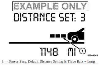
You can change the distance setting by pulling the lever toward you and release (“DISTANCE”). Each time this is done, the distance setting toggles between long, medium, and short. If there is no vehicle ahead, the vehicle will maintain the set speed. If a slower moving vehicle is detected in the same lane, the EVIC displays the “Sensed Vehicle Indicator” icon, and the system adjusts vehicle speed automatically to maintain the distance setting, regardless of the set speed.
The vehicle will then maintain the set distance until:
• The vehicle ahead accelerates to a speed above the set speed.
• The vehicle ahead moves out of your lane or view of the sensor.
• The vehicle ahead slows to a speed below 18 mph (26 km/h) and the system automatically disables itself.
• The distance setting is changed.
• The system disengages. ( information on ACC Activation). The maximum braking applied by ACC is limited; however, the driver can always apply the brakes manually, if necessary.
A Proximity Warning will alert the driver if ACC predicts that its maximum braking level is not sufficient to maintain the set distance. If this occurs, a visual alert (“ATTENTION”) will flash in the EVIC and a chime will sound while ACC continues to apply its maximum braking capacity. When this occurs, you should immediately apply the brakes as needed to maintain a safe distance from the vehicle ahead.

Adaptive Cruise Control (ACC) Menu
The EVIC displays the current ACC system settings. The EVIC is located in the upper part of the instrument cluster between the speedometer and the tachometer. The information it displays depends on ACC system status.

ACC OFF
− When ACC is deactivated, the display will read “ACC OFF.”

ACC READY
− When ACC is activated, the display will read “ACC READY.”
ACC SET
− When ACC is set, the set speed will display.

The set speed will continue to display in place of the odometer reading when changing the EVIC display while ACC is set.

The ACC SET screen will display once again if any ACC activity occurs, which may include any of the following:
• Set speed change
• Distance setting change
• System cancel
• Acquisition/loss of Target
• Driver override
System off
• Proximity warning
• ACC unavailable/service ACC warning
The EVIC will return to the last display selected after 5 seconds of no ACC activity.
Display Warnings & Maintenance
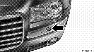
ACC Unavailable Warning
The ACC Unavailable Warning will display when conditions temporarily limit system performance. This most often occurs at times of poor visibility, such as in snow, fog, heavy rain, or when driving into direct sunlight (sunrise or sunset). The ACC system may also become temporarily unavailable due to obstructions, such as dirt or ice. In these cases, the EVIC will display “ACC UNAVAILABLE.”
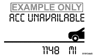
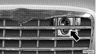
If weather conditions are not a factor, the driver should examine the sensor. It may require cleaning or removal of an obstruction. The sensor is located behind the grille, slightly offset from the center of the grille.
To keep the ACC System operating properly, it is important to note the following maintenance items:
• Always keep the sensor clean. Carefully wipe the sensor lens with a soft cloth. Be cautious not to damage the sensor lens.
• Do not remove any screws from the sensor or the sensor mount. Doing so could cause an ACC system malfunction or failure and require a sensor realignment.
• If the sensor is damaged due to an accident, see your authorized dealer for service.
• Do not attach or install any accessories near the sensor, including transparent material or aftermarket grilles. Doing so could cause an ACC system failure or malfunction.
When the condition that deactivated the system is no longer present, the system will return to the “ACC Off” state and will resume function by simply reactivating it.
NOTE: Installing a vehicle front-end protector or an aftermarket grille or modifying the grille is not recommended. Doing so may block the sensor and inhibit ACC operation.
Service ACC Warning
If the system turns off, and the EVIC displays “SERVICE ACC,” it indicates there is an internal system fault that requires service from an authorized dealer.
Precautions While Driving with ACC
In certain driving situations, ACC may have detection issues. In these cases, ACC may brake late or unexpectedly. The driver needs to stay alert and may need to intervene.
Offset Driving
ACC may not detect a vehicle in the same lane that is offset from your direct line of travel. There will not be sufficient distance to the vehicle ahead. The offset vehicle may move in and out of the line of travel, which can cause your vehicle to brake or accelerate unexpectedly.

Turns and Bends
In turns or bends, ACC may detect a vehicle ahead too late or too early. This may cause your vehicle to brake late or unexpectedly. Give extra attention in curves and be ready to apply the brakes if necessary. Be sure to select an appropriate speed while driving in curves.

ACC may occasionally provide braking and/or a driver alert that you consider unnecessary. This may be the system’s response to signs, guardrails, and other stationary objects in a curve. This is normal operation and your vehicle does not require service.
Lane Changing ACC will not detect a vehicle until it is completely in the lane in which you are travelling. In the illustration shown, ACC has not yet detected the vehicle changing lanes, and it will not until it may be too late to take action. ACC will not detect a vehicle until it is completely in the lane. There will not be sufficient distance to the lanechanging vehicle. Always be attentive and ready to apply the brakes if necessary.

Using ACC on Hills
When driving on hills, ACC may not detect a vehicle in your lane. Depending on the speed, vehicle load, traffic conditions, and the steepness of the hills, ACC performance may be limited.

Narrow Vehicles
Some narrow vehicles traveling near the outer edges of the lane or edging into the lane are not detected until they have moved fully into the lane. There will not be sufficient distance to the vehicle ahead.
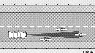
General Information

REAR PARK ASSIST SYSTEM — IF EQUIPPED
The Rear Park Assist System is a driver aid that senses for obstacles behind the vehicle. Refer to the Warnings, Cautions, and Notes in this section for system limitations and usage recommendations. The Rear Park Assist System is active when the driver shifts the transmission into the R (Reverse) position, and the parking brake is not applied, and the vehicle speed is less than 10 mph (16 km/h). The system can be turned on or off when the vehicle is in PARK through the Electronic Vehicle Information Center (EVIC) — if equipped. For details,“Personal Settings (Customer Programmable Features)” under “Electronic Vehicle Information Center (EVIC)” in Section 4 of this manual.
The system uses four sensors located in the rear bumper to scan for obstacles up to 59 inches (150 cm) away from the rear bumper fascia. The warning display located above the rear window provides both visible and audible warnings to indicate the range of the object.

The warning display contains two sets of yellow and red LEDs, one set to warn of obstacles behind the left rear of the vehicle and the other set to warn of obstacles behind the right rear of the vehicle. The driver can view the LEDs either through the rear view mirror or by looking at the display above the rear window. The system dimly illuminates the two outer most yellow LEDs when it is ON and detecting no obstacles. The following chart shows the warning display operation when the system is detecting an obstacle:
WARNING DISPLAY DISTANCES

NOTE: The Rear Park Assist system will MUTE the radio, if on, when the system is sounding an audio tone.
WARNING!
• Drivers must be careful when backing up even when using the Rear Park Assist System. Always check carefully behind your vehicle, look behind you, and be sure to check for pedestrians, animals, other vehicles, obstructions, and blind spots before backing up. You are responsible for safety and must continue to pay attention to your surroundings. Failure to do so can result in serious injury or death.
• Before using the Rear Park Assist System, it is strongly recommended that the ball mount and hitch ball assembly is disconnected from the vehicle when the vehicle is not used for towing. Failure to do so can result in injury or damage to vehicles or obstacles because the hitch ball will be much closer to the obstacle than the rear fascia when the warning display turns the red LEDs ON. Also, the sensors could detect the ball mount and hitch ball assembly, depending on its size and shape, giving a false indication that an obstacle is behind the vehicle.
CAUTION!
• The Rear Park Assist System is only a parking aid and it is unable to recognize every obstacle, including small obstacles. Parking curbs might be temporarily detected or not detected at all. Obstacles located above or below the sensors will not be detected when they are in close proximity.
• The vehicle must be driven slowly when using the Rear Park Assist System to be able to stop in time when the obstacle is detected. It is recommended that the driver looks over his/her shoulder when using the Rear Park Assist System.
NOTE:
• Ensure that the rear bumper is free of dirt and debris to keep the system operating properly.
• Jackhammers, large trucks, and other vibrations could affect the performance of the system.
If “Service Park Assist System” appears in the Electronic Vehicle Information Center (EVIC) after making sure the rear bumper is clean please see your authorized dealer.
OVERHEAD CONSOLE
The overhead console contains courtesy/reading lights, an optional universal garage door opener (HomeLink), storage for sunglasses, and an optional power sunroof switch.
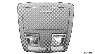
Courtesy/Reading Lights
At the forward end of the console are two courtesy/ reading lights. Press the lens to turn on the light. Press it a second time to turn off the light. These lights also turn on when a door is opened, or when the unlock button on the remote keyless entry transmitter is pressed, or when the dimmer control is turned fully upward, past the second detent.
Sunglasses Storage
At the rear of the console, a compartment is provided for the storage of a pair of sunglasses. The storage compartment access is a push/push design. Push the finger depression on the overhead console to open. Push the finger depression to close.
GARAGE DOOR OPENER (HomeLink) — IF EQUIPPED
The HomeLink Universal Transceiver replaces up to three remote controls (hand held transmitters) that operate devices such as garage door openers, motorized gates, or home lighting. It triggers these devices at the push of a button. The Universal Transceiver operates off your vehicle’s battery and charging system; no batteries are needed.
NOTE: The HomeLink Universal Transceiver is disabled when the Vehicle Security Alarm is active. For additional information on HomeLink, call 1–800– 355–3515, or on the internet at www.homelink.com.
WARNING!
• A moving garage door can cause injury to people and pets in the path of the door. People or pets could be seriously or fatally injured. Only use this transceiver with a garage door opener that has a “stop and reverse” feature as required by federal safety standards. This includes most garage door opener models manufactured after 1982. Do not use a garage door opener without these safety features it could cause injury or death. Call tollfree 1–800–355–3515 or, on the Internet at www.homelink.com for safety information or assistance.
• Vehicle exhaust contains carbon monoxide, a dangerous gas. Do not run the vehicle’s exhaust while training the transceiver. Exhaust gas can cause serious injury or death.
• Your motorized door or gate will open and close while you are training the Universal Transceiver. Do not train the transceiver if people or pets are in the path of the door or gate. A moving door or gate can cause serious injury or death to people and pets or damage to objects.
Programming HomeLink
NOTE: When programming a garage door opener, it is advised to park outside the garage. It is also recommended that you install a new battery in the hand-held transmitter of the device being programmed. This will allow for quicker training and accurate transmission of the radio-frequency signal. The Electronic Vehicle Information Center (EVIC) features a driver-interactive display, which includes HomeLink system messages. The EVIC is located in the upper part of the cluster between the speedometer and tachometer.

1. Press and hold the two outer HomeLink buttons. Release the buttons only when the EVIC displays “Channels Cleared” (after 20 seconds); however, do not hold the buttons for longer than 30 seconds. Do not repeat this step if programming a second or third hand-held transmitter to the remaining HomeLink buttons.

2. Position the end of your hand-held transmitter 1-3 inches (3-8 cm) away from the HomeLink buttons.
3. Simultaneously press and hold the HomeLink button (that you want to train) and the hand-held transmitter button. Do not release the buttons until Step 4 is complete.
NOTE: Some gate operators and garage door openers may require you to replace this Programming Step 3 with procedures noted under Gate Operator/Canadian Programming.
4. The EVIC will display “Channel X Training” (where X is Channel 1, 2, or 3). Release both buttons after the EVIC displays “Channel X Trained.”
NOTE: If the EVIC displays “Did Not Train,” repeat Steps 2–4.
5. Press and hold the just trained HomeLink button and observe the EVIC display. If the EVIC displays “Channel X Transmit” (where X is Channel 1, 2, or 3), then programming is complete, and your device should activate when the HomeLink button is pressed and released.
NOTE: To program the remaining two HomeLink buttons, begin with Programming Step 2. Do not repeat Step 1.
NOTE: If your garage door opener fails to respond to the programmed HomeLink Universal Transceiver, and your garage door opener is manufactured after 1995, it may have a multiple security code system (rolling code system). Please proceed to Steps 6–8 to complete the programming of a rolling code equipped device (most common garage door openers require this step.
6. At the garage door opener receiver (motor-head unit) in the garage, locate the learn or smart button. This can usually be found where the hanging antenna wire is attached to the motor-head unit.
7. Firmly press and release the learn or smart button. (The name and color of the button may vary by manufacturer.) NOTE: You will have 30 seconds in which to initiate Step 8.
8. Return to the vehicle and firmly press, hold for two seconds, and release the programmed HomeLink button. Repeat the press/hold/release sequence a second time, and, depending on the brand of the garage door opener (or other rolling code equipped device), repeat this sequence a third time to complete the programming. HomeLink should now activate your rolling code equipped device.
NOTE: To program the remaining two HomeLink buttons, begin with Programming Step 2. Do not repeat Step 1. For questions or comments, please contact HomeLink at www.homelink.com or 1-800-355-3515.
Canadian Programming/Gate Programming
Canadian radio-frequency laws require transmitter signals to time-out (or quit) after several seconds of transmission, which may not be long enough for HomeLink to pick up the signal during programming. Similar to this Canadian law, some U.S. gate operators are designed to time-out in the same manner. If you live in Canada or you are having difficulties programming a gate operator by using the Programming procedures (regardless of where you live), replace Programming HomeLink Step 3 with the following:
NOTE: If programming a garage door opener or gate operator, it is advised to unplug the device during the cycling process to prevent possible overheating. 3. Continue to press and hold the HomeLink button while you press and release your hand-held transmitter every two seconds until the frequency signal is accepted successfully by HomeLink. The EVIC will display “Channel X Trained” (where X is Channel 1, 2, or 3). Proceed with Programming Step 4 to complete the procedure.
Using HomeLink
To operate, simply press and release the programmed HomeLink button. Activation will now occur for the trained device (i.e. garage door opener, gate operator, security system, entry door lock, home/office lighting, etc.). For convenience, the hand-held transmitter of the device may also be used at any time. In the event that there are still programming difficulties or questions, contact HomeLink at: www.homelink.com or 1-800-355- 3515.
Erasing HomeLink Buttons
To erase programming from the three buttons (individual buttons cannot be erased but can be reprogrammed – note below), follow the step noted:
• Press and hold the two outer HomeLink buttons. Release the buttons only when the EVIC displays “Channels Cleared” (after 20 seconds); however, do not hold the buttons for longer than 30 seconds. HomeLink is now in the train (or learning) mode and can be programmed at any time beginning with Programming Step 2.
Reprogramming a Single HomeLink Button
To program a device a previously trained HomeLink button, follow these steps:
1. Press and hold the desired HomeLink button. Do NOT release the button.
2. The EVIC will display “Channel X Transmit” (where X is Channel 1, 2, or 3) for 20 seconds and then change to “Channel X Training.” Without releasing the HomeLink button, proceed with Programming Step 2.
For questions or comments, contact HomeLink at www.homelink.com or 1-800-355-3515.
Security
If you sell your vehicle, be sure to erase the frequencies by following the “Erasing HomeLink Buttons” instructions in this section. This device complies with part 15 of FCC rules and with RSS-210 of Industry Canada. Operation is subject to the following conditions:
• This device may not cause harmful interference.
• This device must accept any interference that may be received including interference that may cause undesired operation.
NOTE: Changes or modifications not expressly approved by the party responsible for compliance could void the user’s authority to operate the equipment. HomeLink is a trademark owned by Johnson Controls, Inc.
POWER SUNROOF — IF EQUIPPED
The power sunroof switch is located between the sun visors on the overhead console.

WARNING!
• Never leave children in a vehicle, with the keys in the ignition switch. Occupants, particularly unattended children, can become entrapped by the power sunroof while operating the power sunroof switch. Such entrapment may result in serious injury or death.
• In an accident, there is a greater risk of being thrown from a vehicle with an open sunroof. You could also be seriously injured or killed. Always fasten your seat belt properly and make sure all passengers are properly secured too.
• Do not allow small children to operate the sunroof. Never allow fingers or other body parts, or any object to project through the sunroof opening. Injury may result.
Opening Sunroof – Express
Press the switch rearward and release, and the sunroof will open automatically from any position. The sunroof will open fully and then stop automatically. This is called Express Open. During Express Open operation, any movement of the sunroof switch will stop the sunroof.
Closing Sunroof – Express
Press the switch forward and release, and the sunroof will close automatically from any position. The sunroof will close fully and stop automatically. This is called Express Close. During Express Close operation, any movement of the switch will stop the sunroof.
Pinch Protect Feature
This feature will detect an obstruction in the opening of the sunroof during Express Close operation. If an obstruction in the path of the sunroof is detected, the sunroof will automatically retract. Remove the obstruction if this occurs. Next, press the switch forward and release to Express Close.
Pinch Protect Override
If a known obstruction (ice, debris, etc.) prevents closing, press the switch forward and hold for two seconds after the reversal occurs. This allows the sunroof to move towards the closed position.
NOTE: Pinch protection is disabled while the switch is pressed.
Venting Sunroof – Express
Press and release the V button, and the sunroof will open to the vent position. This is called Express Vent, which operates regardless of sunroof position. During Express Vent operation, any movement of the switch will stop the sunroof.
Sunshade Operation
The sunshade can be opened manually. However, the sunshade will open automatically as the sunroof opens.
NOTE: The sunshade cannot be closed if the sunroof is open.
Wind Buffeting
Wind buffeting can be described as the perception of pressure on the ears or a helicopter type sound in the ears. Your vehicle may exhibit wind buffeting with the windows down, or the sunroof (if equipped) in certain open or partially open positions. This is a normal occurrence and can be minimized. If the buffeting occurs with the rear windows open, then open the front and rear windows together to minimize the buffeting. If the buffeting occurs with the sunroof open, then adjust the sunroof opening to minimize the buffeting or open any window.
Sunroof Maintenance
Use only a non-abrasive cleaner and a soft cloth to clean the glass panel.
Ignition Off Operation
For vehicles not equipped with the Electronic Vehicle Information Center (EVIC), the power sunroof switch will remain active for 10 minutes after the ignition switch is turned off. Opening either front door will cancel this feature.
For vehicles equipped with the EVIC, the power sunroof switch will remain active for up to 60 minutes after the ignition switch is turned off. Opening either front door will cancel this feature. The time is programmable. For details, “Delay Power Off to Accessories Until Exit,” under “Personal Settings (Customer Programmable Features),” under “Electronic Vehicle Information Center (EVIC)” in Section 4 of this manual.
Sunroof Fully Closed
Press the switch forward and release to ensure that the sunroof is fully closed.
ELECTRICAL POWER OUTLETS
There are two 12-volt electrical outlets on this vehicle. Both of the outlets are protected by a fuse. The 12-volt power outlet next to the ash receiver tray (if equipped with an optional Smoker’s Package) has power available only when the ignition is on. This outlet will also operate a conventional cigar lighter unit.
WARNING!
Do not place ashes inside the cubby bin located on the center console on vehicles not equipped with the ash receiver tray. A fire leading to bodily injury could result.
NOTE: If desired, the power outlet next to the ash receiver tray (if equipped) can be converted by your authorized dealer to provide power with the ignition switch in the LOCK position.

The center console outlet is powered directly from the battery (power available at all times). Items plugged into this outlet may discharge the battery and/or prevent engine starting.
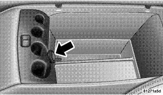
Electrical Outlet Use With Engine Off
CAUTION!
• Many accessories that can be plugged in draw power from the vehicle’s battery, even when not in use (i.e. cellular phones, etc.). Eventually, if plugged in long enough, the vehicle’s battery will discharge sufficiently to degrade battery life and/or prevent engine starting.
• Accessories that draw higher power (i.e. coolers, vacuum cleaners, lights, etc.); will degrade the battery even more quickly. Only use these intermittently and with greater caution.
• After the use of high power draw accessories, or long periods of the vehicle not being started (with accessories still plugged in), the vehicle must be driven a sufficient length of time to allow the alternator to recharge the vehicle’s battery.
• Power outlets are designed for accessory plugs only. Do not hang any type of accessory or accessory bracket from the plug. Improper use of the power outlet can cause damage not covered by your warranty
CUP HOLDERS
Front Seat Cup Holders — Standard
The cup holders are located in the forward edge of the center console.
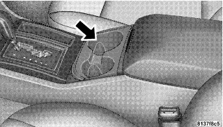
Front Seat Cup Holders — 300 Touring and 300C Models
The cup holders are located in the forward edge of the center console. Push down on the cover as shown to expose the cup holders. Close the cover when the cup holders are no longer needed.

Rear Seat Cup Holders
The rear seat cup holders are located in the center armrest between the rear seats. The cup holders are positioned forward in the armrest and side-by-side to provide convenient access to beverage cans or bottles while maintaining a resting place for the rear occupants’ elbows.
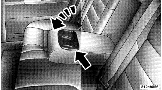
STORAGE
Console Features
The center console contains a large storage bin. The storage bin contains a four-slot coin holder (designed to hold various size coins) and a rubber mat at the bottom of the bin for noise control. The bin is large enough to hold a portable AC/DC converter to power laptops, games, or other electrical equipment. Two slots at the top right side of the bin provide clearance for power cords to pass conveniently out of the bin with the lid closed. This feature is ideal for games, laptops, cell phones, or other electrical equipment. The console’s front-opening lid allows for easy access to the storage bin for the both the driver and the front passenger. The inside portion of the arm rest lid contains a penholder, a tissue holder, and a tire gauge holder. In addition to the internal storage, the console contains two shift bezel cubby bins with rubber mats for holding small items. For vehicles not equipped with navigation radio, the console also contains an extra storage bin located below the climate control, which holds up to four CD jewel cases.
Cargo Area
The 60/40 split-folding rear seat provides cargo-carrying versatility. The seatbacks fold down easily by pulling nylon tabs between the seatbacks and the bolsters. When the seats are folded down, they provide a continuous, nearly flat extension of the load floor. When the seatback is folded to the upright position, make sure it is latched by strongly pulling on the top of the seatback above the seat strap.
WARNING!
• Be certain that the seatback is securely locked into position. If the seatback in not securely locked into position, the seat will not provide the proper stability for child seats and/or passengers. An improperly latched seat could cause serious injury.
• The cargo area in the rear of the vehicle (with the rear seatbacks in the locked-up or folded down position) should not be used as a play area by children when the vehicle is in motion. They could be seriously injured in an accident. Children should be seated and using the proper restraint system.
• To help protect against personal injury, passengers should not be seated in the rear cargo area. The rear cargo space is intended for load carrying purposes only, not for passengers, who should sit in seats and use seat belts.
WARNING!
• The weight and position of cargo and passengers can change the vehicle center of gravity and vehicle handling. To avoid loss of control resulting in personal injury, follow these guidelines for loading your vehicle:
• Always place cargo evenly on the cargo floor. Put heavier objects as low and as far forward as possible.
• Place as much cargo as possible in front of the rear axle. Too much weight or improperly placed weight over or behind the rear axle can cause the rear of the vehicle to sway.
• Do not pile luggage or cargo higher than the top of the seatback. This could impair visibility or become a dangerous projectile in a sudden stop or collision.
LOAD LEVELING SYSTEM — IF EQUIPPED
The automatic load leveling system will provide a levelriding vehicle under most passenger and cargo loading conditions. A hydraulic pump contained within the shock absorbers raises the rear of the vehicle to the correct height. It takes approximately 1 mile (1.6 km) of driving for the leveling to complete depending on road surface conditions. If the leveled vehicle is not moved for approximately 15 hours, the leveling system will bleed itself down. The vehicle must be driven to reset the system.