Page Contents
- 1 Starting Procedures
- 2 ENGINE BLOCK HEATER — IF EQUIPPED
- 3 AUTOMATIC TRANSMISSION
- 4 AUTOSTICK — IF EQUIPPED
- 5 ALL WHEEL DRIVE — IF EQUIPPED
- 6 DRIVING ON SLIPPERY SURFACES
- 7 PARKING BRAKE
- 8 BRAKE SYSTEM
- 9 POWER STEERING
- 10 MULTI DISPLACEMENT SYSTEM (MDS) – 5.7L Engine Only
- 11 TRACTION CONTROL SYSTEM (TCS) — IF EQUIPPED
- 12 ELECTRONIC STABILITY PROGRAM (ESP) — IF EQUIPPED
- 13 TIRE SAFETY INFORMATION
- 14 TIRES — GENERAL INFORMATION
- 15 Tire Pressure
- 16 WARNING!
- 17 SELF–SEALING TIRES — IF EQUIPPED
- 18 TIRE CHAINS
- 19 SNOW TIRES
- 20 TIRE ROTATION RECOMMENDATIONS
- 21 TIRE PRESSURE MONITOR SYSTEM (TPMS) — IF EQUIPPED
- 22 FUEL REQUIREMENTS
- 23 ADDING FUEL
- 24 VEHICLE LOADING
- 25 TRAILER TOWING
- 26 RECREATIONAL TOWING (BEHIND MOTORHOME, ETC.)
Starting Procedures
Before starting your vehicle, adjust your seat, adjust the inside and outside mirrors, fasten your seat belt, and if present, instruct all other occupants to buckle their seat belts.
WARNING!
• Never leave children alone in a vehicle. Leaving children in a vehicle unattended is dangerous for a number of reasons. A child or others could be seriously or fatally injured. Don’t leave the keys in the ignition. A child could operate power windows, other controls, or move the vehicle.
• Do not leave animals or children inside parked vehicles in hot weather; interior heat build up may cause serious injury or death.
• Be sure to turn off the engine if you want to rest or sleep in your car. Accidents can be caused by inadvertently moving the gear selection lever or by pressing the accelerator pedal. This may cause excessive heat in the exhaust system, resulting in overheating and vehicle fire, which may cause serious or fatal injuries.
Automatic Transmission
The gear selector must be in the NEUTRAL or PARK position before you can start the engine. Apply the brakes before shifting into any driving gear.
Normal Starting
Normal Starting of either a cold or a warm engine is obtained without pumping or depressing the accelerator pedal. Turn the key to the “START” position and release when the engine starts. If the engine has not started within 3 seconds, slightly depress the accelerator pedal while continuing to crank. If the engine fails to start within 15 seconds, turn the key to the “LOCK” position, wait 10 to 15 seconds, then repeat the normal starting procedure.
Extremely Cold Weather (below 20°F or 29°C)
To insure reliable starting at these temperatures, use of an externally powered electric engine block heater (available from your dealer) is recommended.
If Engine Fails To Start
If the engine fails to start after you have followed the “NORMAL STARTING” procedure, it may be flooded. Push the accelerator pedal all the way to the floor and hold it there while cranking the engine. This should clear any excess fuel in case the engine is flooded.
CAUTION!
To prevent damage to the starter, do not crank the engine for more than 15 seconds at a time. Wait 10 to 15 seconds before trying again.
WARNING!
• Never pour fuel or other flammable liquid into the throttle body air inlet opening in an attempt to start the vehicle. This could result in flash fire causing serious personal injury.
• Do not attempt to push or tow your vehicle to get it started. Vehicles equipped with an automatic transmission cannot be started this way. Unburned fuel could enter the catalytic converter and once the engine has started, ignite and damage the converter and vehicle. If the vehicle has a discharged battery, booster cables may be used to obtain a start from a booster battery or the battery in another vehicle. This type of start can be dangerous if done improperly. See section 6 of this manual for the proper jump-starting procedures and follow them carefully.
If the engine is flooded, it may start to run, but not have enough power to continue running when the key is released. If this occurs, continue cranking up to 15 seconds with the accelerator pedal pushed all the way to the floor. Release the accelerator pedal and the key once the engine is running smoothly. Do not overspeed the engine. If the engine shows no sign of starting after two 15- second periods of cranking with the accelerator pedal held to the floor, the “NORMAL STARTING” procedure should be repeated.
After Starting
The idle speed is controlled automatically and it will decrease as the engine warms up.
ENGINE BLOCK HEATER — IF EQUIPPED
The engine block heater warms engine coolant and permits quicker starts in cold weather. Connect the cord to a standard 110-115 volt AC electrical outlet with a grounded, three-wire extension cord. The engine block heater cord is routed under the hood on the driver side of the vehicle. It has a removable cap that is located on the driver side of the Integrated Power Module.
WARNING!
Remember to disconnect the cord before driving. Damage to the 110-115 volt electrical cord could cause electrocution.
AUTOMATIC TRANSMISSION
CAUTION!
Damage to the transmission may occur if the following precautions are not observed:
• Shift into PARK only after the vehicle has come to a complete stop.
• Shift into or out of REVERSE only after the vehicle has come to a complete stop and the engine is at idle speed.
• Do not shift from REVERSE, PARK, or NEUTRAL into any forward gear when the engine is above idle speed.
• Before shifting into any gear, make sure your foot is firmly on the brake pedal.
WARNING!
It is dangerous to shift the selector lever out of “P” or “N” if the engine speed is higher than idle speed. If your foot is not firmly on the brake pedal, the vehicle could accelerate quickly forward or in reverse. You could lose control of the vehicle and hit someone or something. Only shift into gear when the engine is idling normally and when your right foot is firmly on the brake pedal.
Automatic Transmission — General Information
The automatic transmission selects individual gears automatically, dependent upon:
• Altitude
• Vehicle Loading
• Driving Style
• Selector lever position
• Accelerator position
• Vehicle speed The gear shifting process is continuously adapted, dependent on the driving style, the driving situation and the road characteristics.
NOTE:
• After selecting any driving position, wait a moment to allow the gear to engage fully before accelerating, especially when the engine is cold.
• If there is a need to restart the engine, be sure to cycle the key to the LOCK position before restarting. Transmission engagement may be delayed up to 10 seconds after restart if the key is not cycled to the LOCK position first.
• The electronically controlled transmission provides a precise shift schedule. The transmission electronics are self-calibrating. Therefore, the first few shifts on a new vehicle may be somewhat abrupt or soft until after the break-in period. This is a normal condition, and precision shifts will develop within a few shift cycles.
The selector lever is automatically locked while in the P (Park) position. To move the selector lever out of the P (Park) position, the brake pedal must be firmly depressed before the shift lock will release. Shift the selector lever to the desired position only when the engine is idling normally and the brake pedal is applied. Do not release the brake until ready to drive. The vehicle may otherwise accelerate quickly when the selector lever is in D (Drive) or R (Reverse) position.
WARNING!
Unintended movement of a vehicle could injure those in and near the vehicle. As with all vehicles, you should never exit a vehicle while the engine is running. Before exiting a vehicle, you should always shift the vehicle into P (Park), remove the key from the ignition, and apply the parking brake. Once the key is removed from the ignition, the transmission selector lever is locked in the P (Park) position, securing the vehicle against unwanted movement. Furthermore, you should never leave children unattended inside a vehicle.
Over Temperature Mode
The transmission electronics constantly monitor the transmission oil temperature. If the transmission exceeds normal operating temperature, the transmission will change the way it shifts to help control the condition. This may result in a slightly different feeling or response during normal operation in D (Drive) position. After the transmission cools down, it will return to normal operation.
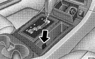
Brake/Transmission Shift Interlock System
This vehicle is equipped with a brake transmission shift interlock system (BTSI) that holds the selector lever in the P (Park) position when the ignition switch is in the LOCK position. To move the selector lever out of the P (Park) position, the ignition switch must be turned to the ON position, and the brake pedal must be depressed.

For electrical system malfunctions, there is an override for the interlock system. In order to override this system the key must be in the ignition with the switch in the ACC or ON positions. Remove the rubber storage tray from the bin located to the right of the selector lever. The override can be activated by pressing the pink-colored tab, which can be accessed through a hole inside the bin. While the override is pressed, the shifter can be moved out of the park position without pressing the brake. After operation, return the rubber storage tray to its original position.
4 Speed Automatic Transmission
Shifting from D (Drive) to P (Park) or R (Reverse) (or from P or R to D) should be done only after the accelerator pedal is released and the vehicle is stopped. Be sure to keep your foot on the brake when moving the selector lever between these gears.

Gear Ranges
P (Park)
P (Park) supplements the parking brake by locking the transmission. The engine can be started in this range. Never use P (Park) while the vehicle is in motion. Apply the parking brake when leaving the vehicle in this range. When parking on a flat surface, place the gear selector in the P (Park) position first, and then apply the parking brake. When parking on a hill, it is important to set the parking brake before placing the gear selector in P (Park), otherwise the load on the transmission locking mechanism may make it difficult to move the selector out of park. As an added precaution, turn the front wheels toward the curb on a downhill grade and away from the curb on an uphill grade.
WARNING!
Never use Park position on an automatic transmission as a substitute for the parking brake. Always apply parking brake fully when parked to guard against vehicle movement and possible injury or damage.
The following indicators should be used to ensure that you have engaged the selector lever into the P (Park) position:
• When shifting into P (Park) move the lever all the way forward until it stops, and is fully seated.
• Look at the shift indicator display on the instrument panel to ensure it is in the P (Park) position.
CAUTION! Damage to the shifter could result if the selector lever is moved out of P (Park) before the ignition is turned from the LOCK to ON position.
R (Reverse)
For moving the vehicle rearward. Always stop before moving the lever to R (Reverse), except when rocking the vehicle.
N (Neutral)
Engine may be started in this range.
CAUTION! Coasting the vehicle, or driving for any other reason with selector lever in NEUTRAL can result in transmission damage.
WARNING!
Do not coast in N (Neutral) and never turn off the ignition to coast down a hill. These are unsafe practices that limit your response to changing traffic or road conditions. You might lose control of the vehicle and have an accident.
D (Overdrive)
This range should be used for most city and highway driving. It provides the smoothest up shifts and down shifts, and the best fuel economy. Select the “3” range when frequent transmission shifting occurs when using the Overdrive range, such as when operating the
vehicle under heavy loading conditions (in hilly terrain, traveling into strong head winds, or while towing heavy trailers.
NOTE:
• If the vehicle is started in cold temperatures, shifts into Overdrive may be delayed. Normal Overdrive and shifting operation will resume when the temperature of the transmission reaches the appropriate temperature. “Note” under “Torque Converter Clutch” later in this section.
• If the transmission temperature gets too hot, the transmission may downshift out of Overdrive or engage overdrive at higher vehicle speeds until the transmission cools down. After cooldown, Overdrive will resume normal operation.
3 (Third)
This range eliminates shifts into Overdrive. The transmission will operate normally in First, Second and Third while in this range. The “3” position should also be used when descending steep grades to prevent brake system distress.
NOTE: Using the “3” range while operating the vehicle under heavy operating conditions will improve performance and extend transmission life by reducing excessive shifting and heat build up.
L (Low)
This range should be used for engine braking when descending very steep grades. In this range, upshifts will occur only to prevent engine overspeed while downshifts occur earlier than other gear range selections.
CAUTION! Never race the engine with the brakes on and the vehicle in gear, and never hold the vehicle on an incline without applying the brakes. These practices can cause overheating and damage to the transmission.
Torque Converter Clutch
A feature designed to improve fuel economy has been added to the automatic transmission of this vehicle. A clutch within the torque converter engages automatically
at calibrated speeds. This may result in a slightly different feeling or response during normal operation in high gear. When the vehicle speed drops, or during acceleration, the clutch automatically and smoothly disengages.
NOTE:
• The torque converter clutch will not engage until the transmission fluid and engine coolant is warm (usually after 1–3 miles (1.6–4.8 km) of driving). Because engine speed is higher when the torque converter clutch is not engaged, it may seem as if the transmission is not shifting into “Overdrive” when cold. This is considered a normal condition. Pulling the selector lever into the “3” position will show that the transmission is able to shift into and out of “Overdrive.”
• If the vehicle has not been driven for several days, the first few seconds of operation after shifting the transmission into gear may seem sluggish. This is due to the transmission fluid partially draining from the torque converter into the transmission. This is considered a normal condition and it will not cause damage to the transmission. The torque converter will refill within 5 seconds of shifting from P (Park) into any other gear position.
Transmission Limp Home Mode
The transmission is monitored for abnormal conditions. If a condition is detected that could cause damage, the transmission automatically shifts into second gear. The transmission remains in second gear despite the forward gear selected. P (Park), R (Reverse), and N (Neutral) will continue to operate. This Reset feature allows the vehicle to be driven to a dealer for service without damaging the transmission. If the problem has been momentary, the transmission can be reset to regain all forward gears.
• Stop the vehicle and shift into P (Park).
• Turn the key to LOCK then start the engine.
• Shift into D (Drive) and resume driving.
NOTE: Even if the transmission can be reset, we recommend that you visit a dealer at your earliest possible convenience. Your dealer has diagnostic equipment to determine if the problem could recur.
If the transmission cannot be reset, dealer service is required.
5 Speed Automatic Transmission
Shifting from D (Drive) to P (Park) or R (Reverse) (or from P or R to D) should be done only after the accelerator pedal is released and the vehicle is stopped. Be sure to keep your foot on the brake when moving the selector lever between these gears.

Gear Ranges
P (Park)
P (Park) supplements the parking brake by locking the transmission. The engine can be started in this range. Never use P (Park) while the vehicle is in motion. Apply the parking brake when leaving the vehicle in this range. When parking on a flat surface, place the gear selector in the P (Park) position first, and then apply the parking brake. When parking on a hill, it is important to set the parking brake before placing the gear selector in P (Park), otherwise the load on the transmission locking mechanism may make it difficult to move the selector out of park. As an added precaution, turn the front wheels toward the curb on a downhill grade and away from the curb on an uphill grade.
WARNING!
Never use Park position on an automatic transmission as a substitute for the parking brake. Always apply parking brake fully when parked to guard against vehicle movement and possible injury or damage.
The following indicators should be used to ensure that you have engaged the selector lever into the P (Park) position:
• When shifting into P (Park) move the lever all the way forward until it stops, and is fully seated.
• Look at the shift indicator display on the instrument panel to ensure it is in the P (Park) position.
CAUTION!
Damage to the shifter could result if the selector lever is moved out of P (Park) before the ignition is turned from the LOCK to ON position.
R (Reverse)
Shift into R (Reverse) gear only when the vehicle is completely stopped.
N (Neutral)
No power is transmitted from the engine to the drive axle. When the brakes are released, the vehicle can be moved freely (pushed or towed). Do not engage N (Neutral) position while driving except to coast when the vehicle is in danger of skidding (e.g., on icy roads). The engine may be started in this range. Use this range for starting your vehicle if it is moving or being towed.
CAUTION!
Coasting the vehicle, or driving for any other reason with selector lever in NEUTRAL can result in transmission damage.
WARNING!
Do not coast in N (Neutral) and never turn off the ignition to coast down a hill. These are unsafe practices that limit your response to changing traffic or road conditions. You might lose control of the vehicle and have an accident.
D (Drive)
This range should be used for most city and highway driving. It provides the smoothest upshifts and downshifts and best fuel economy. The transmission automatically upshifts through fifth gear. The D (Drive) position provides optimum driving characteristics under all normal operating conditions. When frequent transmission shifting occurs when using the Overdrive range, such as when operating the vehicle under heavy loading conditions (in hilly terrain, traveling into strong head winds, or while towing heavy trailers, use the AutoStick mode and select the “3” range.
AutoStick Gear selection
The AutoStick feature can be selected by pressing the selector lever to the right or the left with the lever in the D (Drive) position. The gear currently selected is indicated in the instrument cluster display. Briefly, press the selector lever in the “D -” direction and the transmission will shift from the current gear to the next lower gear. Press and hold the selector lever in the “D-” direction and the transmission will shift from the current gear directly to the next lowest gear for best acceleration.
NOTE: To avoid overrevving the engine when the selector lever is moved in “D -” direction, the transmission will not shift to a lower gear if the engine’s revolutions per minute (RPM) limit would be exceeded. Briefly, press the selector lever in the “D +” direction and the transmission will shift from the current gear to the next higher gear. Press and hold the selector lever in the “D +” direction and the transmission will shift from the current gear directly to gear “D.”
WARNING!
On slippery road surfaces, never downshift in order to obtain braking action. This could result in drive wheel slip and reduced vehicle control. Your vehicle’s ABS will not prevent this type of loss of control. You could lose control of your vehicle and have an accident.
Delayed Shifts in Cold Temperatures
During cold temperature operation, you may notice delayed upshifts depending on engine and transmission temperature as well as vehicle speed. This feature improves warm up time of the engine and transmission to achieve maximum efficiency.
Temporary Transmission Limp Home Mode
The transmission is monitored for abnormal conditions. If a condition is detected that could result in transmission damage, the transmission will engage Limp Home Mode. If vehicle acceleration worsens, or the transmission no longer shifts, the transmission is most likely operating in the Limp Home Mode. In this mode, the transmission will remain in the current gear until the vehicle is brought to a stop. After the vehicle has stopped, P (Park), R (Reverse), and N (Neutral) will continue to operate. Second gear will operate in the D (Drive) shifter position. The Malfunction Indicator Light may be illuminated. A reset feature is available to allow the vehicle to be driven to a dealer for service. To reset the transmission, use the following procedure: 1. Stop the vehicle. 2. Move the selector lever to the P (Park) position. 3. Turn off the engine. 4. Wait approximately 10 seconds. 5. Restart the engine. 6. Move the selector lever to the desired range. If the problem is no longer detected, the transmission will return to normal operation.
NOTE: Even if the transmission can be reset, we recommend that you visit a dealer at your earliest
possible convenience. Your dealer has diagnostic equipment to determine if the problem could recur. Have the transmission checked at your authorized dealer as soon as possible. If the problem has been momentary, the transmission can be reset to regain all forward gears.
Permanent Transmission Limp Home Mode
Permanent Limp Home Mode will be activated if the transmission enters temporary Limp Home Mode three times. Follow the reset procedure described under “Temporary Transmission Limp Home Mode” in this section. In Permanent Limp Home Mode, P (Park), R (Reverse), and N (Neutral) will continue to operate. Second gear will operate in the D (Drive) shifter position. The malfunction indicator light may illuminate.
AUTOSTICK — IF EQUIPPED
Autostick is a driver-interactive transmission that offers manual gear shifting to provide you with more control of the vehicle. Autostick allows you to maximize engine braking, eliminate undesirable upshifts and downshifts, and improve overall vehicle performance. This system can also provide you with more control during passing, city driving, cold slippery conditions, mountain driving, trailer towing, and many other situations.
Autostick Operation
By placing the selector lever in the D (Drive) position, it can be moved from side to side. This allows the driver to select a higher or lower range of gears. Moving the selector lever to the Left (-) triggers a downshift and to the Right (+) an upshift. The gear position will display in the instrument cluster on the transmission range indicator. You can shift in or out of the Autostick mode at any time without taking your foot off the accelerator pedal. If you choose the Overdrive mode, the transmission will operate automatically, shifting between the five available gears. When you wish to engage Autostick, simply move the selector lever to the Right or Left (D+/D-) while in the D (Drive) position. The transmission will remain in the current gear until an upshift or downshift is chosen.
ALL WHEEL DRIVE — IF EQUIPPED
This feature provides full time All Wheel Drive (AWD) with Anti-lock Brake System (ABS)/Traction Control. The front wheels provide 38% of the torque, and the rear wheels provide 62% of the torque. The system is automatic with no driver inputs or additional driving skills required.
CAUTION!
All wheels must have the same size and type tires. Unequal tire sizes must not be used. Unequal tire size may cause failure of the front differential and/or the transfer case.
DRIVING ON SLIPPERY SURFACES
Acceleration
Rapid acceleration on snow covered, wet, or other slippery surfaces may cause the rear wheels to pull erratically to the right or left. This phenomenon occurs when there is a difference in the surface traction under the rear (driving) wheels.
WARNING!
Rapid acceleration on slippery surfaces is dangerous. Unequal traction can cause sudden pulling of the rear wheels. You could lose control of the vehicle and possibly have an accident. Accelerate slowly and carefully whenever there is likely to be poor traction (ice, snow, wet mud, loose sand, etc.).
Traction
When driving on wet or slushy roads, it is possible for a wedge of water to build up between the tire and road surface. This is known as hydroplaning and may cause partial or complete loss of vehicle control and stopping ability. To reduce this possibility, the following precautions should be observed:
1. Slow down during rainstorms or when the roads are slushy.
2. Slow down if road has standing water or puddles.
3. Replace tires when tread wear indicators first become visible.
4. Keep tires properly inflated.
5. Maintain sufficient distance between your vehicle and the vehicle in front to avoid a collision in a sudden stop.
PARKING BRAKE
The parking brake should always be applied when the driver is not in the vehicle.
WARNING!
Never use Park position on an automatic transmission as a substitute for the parking brake. Always apply parking brake fully when parked to guard against vehicle movement and possible injury or damage.
When parking on a flat surface, place the gear selector in the P (Park) position first, and then apply the parking brake. When parking on a hill, it is important to apply the parking brake before placing the gear selector in P (Park), otherwise the load on the transmission locking mechanism may make it difficult to move the selector out of park. As an added precaution, turn the front wheels toward the curb on a downhill grade and away from the curb on an uphill grade.
The foot operated parking brake is positioned below the lower left corner of the instrument panel. To apply the parking brake, push the parking brake pedal down and then remove your foot from the pedal. To release the parking brake, push down on the parking brake pedal and then release.

The brake light in the instrument cluster will turn on when the parking brake is applied and the ignition switch is on. NOTE: This light only shows that the parking brake is applied. It does not show the degree of brake application.
WARNING!
• Never leave children alone in a vehicle. Leaving children in a vehicle unattended is dangerous for a number of reasons. A child or others could be seriously or fatally injured. Don’t leave the keys in the ignition. A child could operate power windows, other controls, or move the vehicle.
• Be sure the parking brake is fully disengaged before driving: failure to do so can lead to brake failure, and an accident.
BRAKE SYSTEM

system will still function. There will be some loss of overall braking effectiveness. This may be evident by increased pedal travel during application, greater pedal force required to slow or stop, and potential activation of the Brake Warning Light.
In the event power assist is lost for any reason (for example, repeated brake applications with the engine off) the brakes will still function. The effort required to brake the vehicle will be much greater than that required with the power system operating.
Anti-Lock Brake System — If Equipped
The Anti-Lock Brake System provides increased vehicle stability and brake performance under most braking conditions. The system automatically “pumps” the brakes during severe braking conditions to prevent wheel lock-up. The electronic brake force distribution (EBD) prevents the rear wheels from over-braking and provides greater control of available braking forces applied to the rear axle. When the vehicle is driven over 7 mph (11 km/h), you may also hear a slight clicking sound as well as some related motor noises. These noises are the system performing its self check cycle to ensure that the ABS system is working properly. This self check occurs each time the vehicle is started and accelerated past 7 mph (11 km/h). ABS is activated during braking under certain road or stopping conditions. ABS-inducing conditions can include ice, snow, gravel, bumps, railroad tracks, loose debris, or panic stops.
You also may experience the following when the brake system goes into Anti-lock:
• The ABS motor running (it may continue to run for a short time after the stop),
• the clicking sound of solenoid valves,
• brake pedal pulsations,
• and a slight drop or fall away of the brake pedal at the end of the stop.
These are all normal characteristics of ABS.
WARNING!
• The Anti-Lock Brake System contains sophisticated electronic equipment that may be susceptible to interference caused by improperly installed or high output radio transmitting equipment. This interference can cause possible loss of anti-lock braking capability. Installation of such equipment should be performed by qualified professionals.
• Pumping of the Anti-Lock Brakes will diminish their effectiveness and may lead to an accident. Pumping makes the stopping distance longer. Just press firmly on your brake pedal when you need to slow down or stop.
• Anti-lock system (ABS) cannot prevent the natural laws of physics from acting on the vehicle, nor can it increase braking or steering efficiency beyond that afforded by the condition of the vehicle brakes and tires or the traction afforded.
• The ABS cannot prevent accidents, including those resulting from excessive speed in turns, following another vehicle too closely, or hydroplaning. Only a safe, attentive, and skillful driver can prevent accidents.
• The capabilities of an ABS equipped vehicle must never be exploited in a reckless or dangerous manner, which could jeopardize the user’s safety or the safety of others.
All vehicle wheels and tires must be the same size and type and tires must be properly inflated to produce accurate signals for the computer.
Anti-Lock Brake Light

If the ABS light remains on or comes on while driving, it indicates that the Anti-Lock portion of the brake system is not functioning and that service is required. However, the conventional brake system will continue to operate normally if the BRAKE warning light is not on. If the ABS light is on, the brake system should be serviced as soon as possible to restore the benefits of Anti-Lock brakes. If the ABS light does not come on when the Ignition switch is turned to the ON position, have the bulb repaired as soon as possible. If both the Brake Warning Light and the ABS Light remain on, the Anti-Lock brakes (ABS) and Electronic Brake Force Distribution (EBD) systems are not functioning. Immediate repair to the ABS system is required.
POWER STEERING
The standard power steering system will give you good vehicle response and increased ease of maneuverability in tight spaces. The system will provide mechanical steering capability if power assist is lost. If for some reason the power assist is interrupted, it will still be possible to steer your vehicle. Under these conditions, you will observe a substantial increase in steering effort, especially at very low vehicle speeds and during parking maneuvers. NOTE: Increased noise levels at the end of the steering wheel travel are considered normal and do not indicate that there is a problem with the power steering system. Upon initial start-up in cold weather, the power steering pump may make noise for a short amount of time. This is due to the cold, thick fluid in the steering system. This noise should be considered normal, and does not in any way damage the steering system.
WARNING!
Continued operation with reduced power steering assist could pose a safety risk to yourself and others. Service should be obtained as soon as possible.
CAUTION!
Prolonged operation of the steering system at the end of the steering wheel travel will increase the steering fluid temperature and it should be avoided when possible. Damage to the power steering pump may occur.
MULTI DISPLACEMENT SYSTEM (MDS) – 5.7L Engine Only
This feature offers improved fuel economy by shutting off four of the engine’s eight cylinders during light load and cruise conditions. The system is automatic with no driver inputs or additional driving skills required.
NOTE: The MDS system may take some time to return to full functionality after a battery disconnect.
TRACTION CONTROL SYSTEM (TCS) — IF EQUIPPED
WARNING!
The Traction Control System (TCS) cannot prevent the natural laws of physics from acting on the vehicle, nor can it increase the traction afforded. The TCS cannot prevent accidents, including those resulting from excessive speed in turns, or hydroplaning. Only a safe, attentive, and skillful driver can prevent accidents. The capabilities of a TCSequipped vehicle must never be exploited in a reckless or dangerous manner, which could jeopardize the user’s safety or the safety of others.

wheels begin to spin. This indicates that the TCS is active. If the indicator light begins to flash during acceleration, ease up on the accelerator and apply as little throttle as possible. Be sure to adapt your speed and driving to the prevailing road conditions.
The TCS OFF button is located in the center of the instrument panel. To turn OFF the TCS, momentarily press the button and the TCS Indicator Light will illuminate. To turn the system ON again, momentarily press the TCS OFF button and the indicator light will turn OFF .

NOTE: To improve the vehicle’s traction when driving with snow chains, or starting off in deep snow, sand, or gravel, switch off the TCS by pressing the TCS OFF button.
CAUTION!
When the TCS Indicator Light is illuminated continuously, the TCS is switched off. Avoid spinning one drive wheel. This may cause serious damage to the drive train.
NOTE:
• The Traction Control System comes on each time the ignition switch is turned ON. This will occur even if you used the Traction Control Button to turn OFF the system.
• The Traction Control System will make buzzing or clicking sounds when in operation.
BRAKE ASSIST SYSTEM (BAS) — IF EQUIPPED
WARNING!
The BAS (Brake Assist System) cannot prevent the natural laws of physics from acting on the vehicle, nor can it increase the traction afforded by prevailing road conditions. The BAS cannot prevent accidents, including those resulting from excessive speed in turns, driving on very slippery surfaces, or hydroplaning. Only a safe, attentive, and skillful driver can prevent accidents. The capabilities of a BAS-equipped vehicle must never be exploited in a reckless or dangerous manner, which could jeopardize the user’s safety or the safety of others.
The Brake Assist System (BAS) is standard on vehicles equipped with Electronic Stability Program (ESP). The BAS is designed to optimize the vehicle’s braking capability during emergency braking maneuvers. The system applies optimum pressure to the brakes in emergency braking conditions than might otherwise be afforded solely by the driver’s braking style. This can help reduce braking distances. The BAS complements the Anti-Lock Brake System (ABS). Applying the brakes very quickly results in the best BAS assistance. To receive the benefit of the system, you must apply continuous braking power during the stopping sequence. Do not reduce brake pedal pressure. Once the brake pedal is released, the BAS is deactivated.
ELECTRONIC STABILITY PROGRAM (ESP) — IF EQUIPPED
WARNING!
The ESP (Electronic Stability Program) cannot prevent the natural laws of physics from acting on the vehicle, nor can it increase the traction afforded by prevailing road conditions. The ESP cannot prevent accidents, including those resulting from excessive speed in turns, driving on very slippery surfaces, or hydroplaning. Only a safe, attentive, and skillful driver can prevent accidents. The capabilities of an ESP-equipped vehicle must never be exploited in a reckless or dangerous manner, which could jeopardize the user’s safety or the safety of others.
This system enhances directional control and stability of the vehicle under various driving conditions. The ESP corrects for oversteering and understeering the vehicle by applying the brake of the appropriate wheel. Engine power may also be reduced to assist in counteracting the condition of oversteer or understeer and help the vehicle maintain the desired path. The ESP uses sensors in the vehicle to determine the path that the driver intends to steer the vehicle and compares it to the actual path of the vehicle. When the actual path does not match the intended path, the ESP applies the brake of the appropriate wheel to assist in counteracting the condition of oversteer or understeer.
• Oversteer – when the vehicle is turning more than appropriate for the steering wheel position.
• Understeer – when the vehicle is turning less than appropriate for the steering wheel position.

active. The indicator light also flashes when the TCS is active. If the indicator light begins to flash during acceleration, ease up on the accelerator and apply as little throttle as possible. Be sure to adapt your speed and driving to the prevailing road conditions.
The ESP OFF button is located in the center of the instrument panel. To turn OFF the ESP, momentarily press the ESP OFF button and the ESP/TCS indicator light will illuminate. To turn the system ON again, momentarily press the ESP OFF button and the indicator light will turn OFF.

NOTE: To improve the vehicle’s traction when driving with snow chains, or starting off in deep snow, sand, or gravel, switch off the ESP by pressing the ESP OFF button.
When ESP is switched off, the engine torque reduction feature is cancelled. Therefore, the enhanced vehicle stability offered by ESP is unavailable. However, a feature of the system remains active. This feature controls wheel spin across an axle quite similarly to a limited slip differential. If one wheel on an axle is spinning faster than the other, the system will apply the brake of the spinning wheel and allow more engine torque to be applied to the wheel that is not spinning. This wheel slip control is active at vehicle speeds between approximately 24 mph (40 km/h) and 50 mph (80 km/h).
CAUTION!
When the ESP/TCS indicator light is illuminated continuously, the ESP is switched off. Avoid spinning one drive wheel. This may cause serious damage to the drive train.
CAUTION!
If the vehicle is towed with the front axle raised, the engine must be shut off (key in the ignition switch to the OFF/LOCK or ACC position). Otherwise, the ESP will immediately be engaged and will apply the rear wheel brakes.
Synchronizing ESP

discharged), the ESP/BAS malfunction indicator light may illuminate with the engine running. If this should occur, turn the steering wheel completely to the left and then to the right. The ESP/BAS malfunction indicator light should go out. However, if the light
remains on, have the ESP and BAS checked at your authorized dealer as soon as possible.
ESP/BAS Malfunction Indicator and ESP/TCS Indicator Lights

yellow ESP/TCS indicator light in the instrument cluster both come on when the ignition switch is turned to the “ON” position. They should go out with the engine running.
The system will turn the ESP/BAS malfunction indicator light on continuously while the engine running if it detects a malfunction in either the ESP or the BAS or both. If the light remains on after several ignition cycles, and you have driven the vehicle several miles at speeds greater than 30 mph (48 km/h), and the ESP is synchronized ( Synchronizing ESP), see your authorized dealer as soon as possible to have the problem diagnosed and corrected.
TIRE SAFETY INFORMATION
Tire Markings

NOTE:
• P (Passenger)-Metric tire sizing is based on U.S. design standards. P-Metric tires have the letter “P” molded into the sidewall preceding the size designation. Example: P215/65R15 95H.
• European Metric tire sizing is based on European design standards. Tires designed to this standard have the tire size molded into the sidewall beginning with
the section width. The letter P is absent from this tire size designation. Example: 215/65R15 96H
• LT (Light Truck)-Metric tire sizing is based on U.S. design standards. The size designation for LT-Metric tires is the same as for P-Metric tires except for the letters “LT” that are molded into the sidewall preceding the size designation. Example: LT235/85R16.
• Temporary Spare tires are high-pressure compact spares designed for temporary emergency use only. Tires designed to this standard have the letter “T” molded into the sidewall preceding the size designation. Example: T145/80D18 103M.
• High Flotation tire sizing is based on U.S. design standards and it begins with the tire diameter molded into the sidewall. Example: 31×10.5 R15 LT.
Tire Sizing Chart


Tire Identification Number (TIN)
The TIN may be found on one or both sides of the tire; however, the date code may only be on one side. Tires with white sidewalls will have the full TIN including date code located on the white sidewall side of the tire. Look for the TIN on the outboard side of black sidewall tires as mounted on the vehicle. If the TIN is not found on the outboard side then you will find it on the inboard side of the tire.

Tire Loading and Tire Pressure
Tire Placard Location
NOTE: The proper cold tire inflation pressure is listed on either the face of the driver’s door or the driver’s side “B” pillar.


Tire and Loading Information
This placard tells you important information about the:
1) number of people that can be carried in the vehicle
2) the total weight your vehicle can carry
3) the tire size designed for your vehicle
4) the cold tire inflation pressures for the front, rear and spare tires.
Loading
The vehicle maximum load on the tire must not exceed the load carrying capacity of the tire on your vehicle. You will not exceed the tire’s load carrying capacity if you adhere to the loading conditions, tire size, and cold tire inflation pressures specified on the “Tire and Loading Information” placard and in the “Vehicle Loading” section of this manual.
NOTE: Under a maximum loaded vehicle condition, gross axle weight ratings (GAWR’s) for the front and rear axles must not be exceeded. For further information on GAWR’s, vehicle loading, and trailer towing, “Vehicle Loading” section of this manual. To determine the maximum loading conditions of your vehicle, locate the statement “The combined weight of occupants and cargo should never exceed XXX kg or XXX lbs.” on the Tire and Loading Information placard. The combined weight of occupants, cargo/luggage and trailer tongue weight (if applicable) should never exceed the weight referenced here.
Steps for Determining Correct Load Limit
1. Locate the statement “The combined weight of occupants and cargo should never exceed XXX pounds” on your vehicle’s placard.
2. Determine the combined weight of the driver and passengers that will be riding in your vehicle.
3. Subtract the combined weight of the driver and passengers from XXX kilograms or XXX pounds.
4. The resulting figure equals the available amount of cargo and luggage load capacity. For example, if “XXX” amount equals 1400 lbs. and there will be five 150 lb. passengers in your vehicle, the amount of available cargo and luggage load capacity is 650 lbs. (since 5 x 150 = 750, and 1400 – 750 = 650 lbs.)
5. Determine the combined weight of luggage and cargo being loaded on the vehicle. That weight may not safely exceed the available cargo and luggage load capacity calculated in Step 4.
6. If your vehicle will be towing a trailer, load from your trailer will be transferred to your vehicle. Consult this
manual to determine how this reduces the available cargo and luggage load capacity of your vehicle.
NOTE: The following table shows examples on how to calculate total load, cargo/luggage, and towing capacities of your vehicle with varying seating configurations and number and size of occupants. This table is for illustration purposes only and may not be accurate for the seating and load carry capacity of your vehicle.
NOTE: For the following example, the combined weight of occupants and cargo should never exceed 865 lbs. (392 Kg).

WARNING!
Overloading of your tires is dangerous. Overloading can cause tire failure, affect vehicle handling, and increase your stopping distance. Use tires of the recommended load capacity for your vehicle. Never overload them.
TIRES — GENERAL INFORMATION
Tire Pressure
Proper tire inflation pressure is essential to the safe and satisfactory operation of your vehicle. Three primary areas are affected by improper tire pressure:
1. Safety—
WARNING!
• Improperly inflated tires are dangerous and can cause accidents.
• Under inflation increases tire flexing and can result in tire failure.
• Over inflation reduces a tire’s ability to cushion shock. Objects on the road and chuckholes can cause damage that result in tire failure.
• Unequal tire pressures can cause steering problems. You could lose control of your vehicle.
• Over inflated or under inflated tires can affect vehicle handling and can fail suddenly, resulting in loss of vehicle control.
• Unequal tire pressures from one side of the vehicle to the other can cause the vehicle to drift to the right or left.
• Always drive with each tire inflated to the recommended cold tire inflation pressure.
2. Economy—
Improper inflation pressures can cause uneven wear patterns to develop across the tire tread. These abnormal wear patterns will reduce tread life resulting in a need for earlier tire replacement. Under inflation, also increases tire rolling resistance and results in higher fuel consumption.
3. Ride Comfort and Vehicle Stability— Proper tire inflation contributes to a comfortable ride. Over inflation produces a jarring and uncomfortable ride.
Tire Inflation Pressures
The proper cold tire inflation pressure is listed either on the face of the driver’s door or on the driver’s side “B” pillar. Some vehicles may have Supplemental Tire Pressure Information for vehicle loads that are less than the maximum loaded vehicle condition. These pressure conditions will be found in the “Supplemental Tire Pressure Information” section of this manual.

The pressure should be checked and adjusted as well as inspecting for signs of tire wear or visible damage at least once a month. Use a good quality pocket-type gauge to check tire pressure. Do not make a visual judgement when determining proper inflation. Radial tires may look properly inflated even when they are under inflated.
CAUTION!
After inspecting or adjusting the tire pressure, always reinstall the valve stem cap (if equipped). This will prevent moisture and dirt from entering the valve stem, which could damage the valve stem.
Inflation pressures specified on the placard are always “cold tire inflation pressure.” Cold tire inflation pressure is defined as the tire pressure after the vehicle has not been driven for at least 3 hours, or driven less than 1 mile (1 km) after a 3 hour period. The cold tire inflation pressure must not exceed the maximum inflation pressure molded into the tire sidewall. Check tire pressures more often if subject to a wide range of outdoor temperatures, as tire pressures vary with temperature changes. Tire pressures change by approximately 1 psi (7 kPa) per 12° F (7° C) of air temperature change. Keep this in mind when checking tire pressure inside a garage, especially in the winter. Example: If garage temperature = 68° F (20° C) and the outside temperature = 32° F (0° C) then the cold tire inflation pressure should be increased by 3 psi (21 kPa), which equals 1 psi (7 kPa) for every 12° F (7° C) for this outside temperature condition. Tire pressure may increase from 2 to 6 psi (13 to 40 kPa) during operation. DO NOT reduce this normal pressure build up or your tire pressure will be too low.
Tire Pressures for High Speed Operation
The manufacturer advocates driving at safe speeds within posted speed limits. Where speed limits or conditions are such that the vehicle can be driven at high speeds, maintaining correct tire inflation pressure is very important. Increased tire pressure and reduced vehicle loading may be required for high-speed vehicle operation. Refer to original equipment or an authorized tire dealer for recommended safe operating speeds, loading and cold tire inflation pressures.
WARNING!
High speed driving with your vehicle under maximum load is dangerous. The added strain on your tires could cause them to fail. You could have a serious accident. Don’t drive a vehicle loaded to the maximum capacity at continuous speeds above 75 mph (120 km/h).
Radial-Ply Tires
WARNING!
Combining radial ply tires with other types of tires on your vehicle will cause your vehicle to handle poorly. The instability could cause an accident. Always use radial ply tires in sets of four (or 6, in case of trucks with dual rear wheels). Never combine them with other types of tires.
Cuts and punctures in radial tires are repairable only in the tread area because of sidewall flexing. Consult your authorized tire dealer for radial tire repairs.
Compact Spare Tire — If Equipped
The compact spare is for temporary emergency use with radial tires. It is engineered to be used on your style vehicle only. Since this tire has limited tread life, the original tire should be repaired (or replaced) and reinstalled at the first opportunity.
WARNING!
Temporary use spare tires are for emergency use only. With these tires, do not drive more than 50 mph (80 km/h). Temporary-use spare tires have limited tread life. When the tread is worn to the tread wear indicators, the temporary use spare tire needs to be replaced. Be sure to follow the warnings, which apply to your spare. Failure to do so could result in spare tire failure and loss of vehicle control.
Do not install a wheel cover or attempt to mount a conventional tire on the compact spare wheel, since the wheel is designed specifically for the compact spare. Do not install more than one compact spare tire/wheel on the vehicle at any given time.
CAUTION!
Because of the reduced ground clearance, do not take your vehicle through an automatic car wash with the compact spare installed. Damage to the vehicle may result.
Limited Use Spare — If Equipped
The limited use spare tire is for temporary emergency use on your vehicle. This tire is identified by a limited use spare tire warning label located on the limited use spare tire and wheel assembly. This tire may look like the original equipped tire on the front or rear axle of your vehicle, but it is not. Installation of this limited use spare tire affects vehicle handling. Since it is not the same tire, replace (or repair) the original tire and reinstall on the vehicle at the first opportunity.
WARNING!
The limited use spare tires are for emergency use only. Installation of this limited use spare tire affects vehicle handling. With this tire, do not drive more than 60 mph (100 km/h). Keep inflated to the cold tire inflation pressure listed on either your tire placard or limited use spare tire and wheel assembly. Replace (or repair) the original tire at the first opportunity and reinstall it on your vehicle. Failure to do so could result in loss of vehicle control.
Tire Spinning
When stuck in mud, sand, snow, or ice conditions, do not spin your vehicle’s wheels above 35 mph (55 km/h). Paragraph on “Freeing A Stuck Vehicle” in Section 6 of this manual.
WARNING!
Fast spinning tires can be dangerous. Forces generated by excessive wheel speeds may cause tire damage or failure. A tire could explode and injure someone. Do not spin your vehicle’s wheels faster than 30 mph (48 km/h) for more than 30 seconds continuously when you are stuck, and don’t let anyone near a spinning wheel, no matter what the speed.
Tread Wear Indicators
Tread wear indicators are in the original equipment tires to help you in determining when your tires should be replaced.

These indicators are molded into the bottom of the tread grooves. They will appear as bands when the tread depth becomes 1/16 inch (2 mm). When the tread is worn to the tread wear indicators, the tire should be replaced. Many states have laws requiring tire replacement at this point.
Life of Tire
The service life of a tire is dependent upon varying factors including but not limited to:
• Driving style
• Tire pressure
• Distance driven
WARNING!
Tires and spare tire should be replaced after six years, regardless of the remaining tread. Failure to follow this warning can result in sudden tire failure. You could lose control and have an accident resulting in serious injury or death.
Keep dismounted tires in a cool, dry place with as little exposure to light as possible. Protect tires from contact with oil, grease, and gasoline.
Replacement Tires
The tires on your new vehicle provide a balance of many characteristics. They should be inspected regularly for wear and correct cold tire inflation pressure. The manufacturer strongly recommends that you use tires equivalent to the originals in size, quality and performance when replacement is needed ( paragraph on “Tread Wear Indicators”). “Tire and Loading Information” placard for the size designation of your tire. The service description and load identification will be found on the original equipment tire. Failure to use equivalent replacement tires may adversely affect the safety, handling, and ride of your vehicle. We recommend that you contact your original equipment or an authorized tire dealer with any questions you may have on tire specifications or capability.
WARNING!
• Do not use a tire, wheel size or rating other than that specified for your vehicle. Some combinations of unapproved tires and wheels may change suspension dimensions and performance characteristics, resulting in changes to steering, handling, and braking of your vehicle. This can cause unpredictable handling and stress to steering and suspension components. You could lose control and have an accident resulting in serious injury or death. Use only the tire and wheel sizes with load ratings approved for your vehicle.
• Never use a tire with a smaller load index or capacity, other than what was originally equipped on your vehicle. Using a tire with a smaller load index could result in tire overloading and failure. You could lose control and have an accident.
• Failure to equip your vehicle with tires having adequate speed capability can result in sudden tire failure and loss of vehicle control.
CAUTION!
Replacing original tires with tires of a different size may result in false speedometer and odometer readings.
Alignment And Balance
Poor suspension alignment may result in:
• Fast tire wear.
• Uneven tire wear, such as feathering and one-sided wear.
• Vehicle pull to right or left.
Tires may also cause the vehicle to pull to the left or right. Alignment will not correct this condition. See your dealer for proper diagnosis. Improper alignment will not cause vehicle vibration. Vibration may be a result of tire and wheel out-ofbalance. Proper balancing will reduce vibration and avoid tire cupping and spotty wear.
SELF–SEALING TIRES — IF EQUIPPED
A non-hardening viscous sealant applied to the inner liner of each tire fills punctures up to 0.19 in. (5 mm) to minimize the loss of air pressure. This contributes to the safety of the vehicle by significantly reducing the probability of a roadside stop due to a flat tire.
TIRE CHAINS
Use only compact chains, or other traction aids that meet SAE type “Class S” specifications. Chains must be the proper size for the vehicle, as recommended by the chain manufacturer.
NOTE: Do not use tire chains on a compact spare tire.
CAUTION!
To avoid damage to your vehicle or tires, observe the following precautions:
• Because of restricted chain clearance between tires and other suspension components, it is important that only chains in good condition are used. Broken chains can cause serious damage. Stop the vehicle immediately if noise occurs that could indicate chain breakage. Remove the damaged parts of the chain before further use.
• Install chains on the rear wheels as tightly as possible and then retighten after driving about 1⁄2 mile (0.8 km).
• Do not exceed 30 mph (48 km/h).
• Drive cautiously and avoid severe turns and large bumps, especially with a loaded vehicle.
• Use on Rear Wheels only.
• Do not drive for prolonged period on dry pavement.
• Observe the tire chain manufacturer’s instructions on the method of installation, operating speed, and conditions for use. Always use the lower suggested operating speed of the chain manufacturer if different from the speed recommended by the manufacture.
NOTE: In order to avoid damage to tires, chains, and your vehicle do not drive for a prolonged period of time on dry pavement. Observe the tire chain manufacturer’s instructions on method of installation, operating speed, and conditions for usage. Always use the lower suggested operating speed if both the chain manufacturer and vehicle manufacture suggest a maximum speed. This notice applies to all chain traction devices, including link and cable (radial) chains.
SNOW TIRES
Some areas of the country require the use of snow tires during winter. Standard tires are of the all season type and satisfy this requirement as indicated by the M+S designation on the tire sidewall. If you need snow tires, select tires equivalent in size and type to the original equipment tires. Use snow tires only in sets of 4, failure to do so may adversely affect the safety and handling of your vehicle. Snow tires generally have lower speed ratings than what was originally equipped with your vehicle and should not be operated at sustained speeds over 75 mph (120 km/h).
TIRE ROTATION RECOMMENDATIONS
Tires on the front and rear axles of vehicles operate at different loads and perform different steering, driving, and braking functions. For these reasons, they wear at unequal rates, and tend to develop irregular wear patterns. These effects can be reduced by timely rotation of tires. The benefits of rotation are especially worthwhile with aggressive tread designs such as those on all season type tires. Rotation will increase tread life, help to maintain mud, snow, and wet traction levels, and contribute to a smooth, quiet ride.
Follow the “Maintenance Schedules” in Section 8 of this manual for the recommended tire rotation frequency for your type of driving. Remember, more frequent rotation is permissible if desired. Also, correct for anything causing rapid or unusual wear prior to performing the tire rotation. The suggested rotation method is the “forward-cross” shown in the following diagram.

TIRE PRESSURE MONITOR SYSTEM (TPMS) — IF EQUIPPED
• The Tire Pressure Monitor System (TPMS) will warn the driver of a low tire pressure based on the vehicle recommended cold placard pressure.
• The tire pressure will vary with temperature by about 1 psi (6.9 kPa) for every 12°F (6.5°C). This means that when the outside temperature decreases, the tire pressure will decrease. Tire pressure should always be set based on cold inflation tire pressure. This is defined as the tire pressure after the vehicle has not been driven for at least 3 hours, or driven less than 1 mile (1 km) after a 3 hour period. The cold tire inflation pressure must not exceed the maximum inflation pressure molded into the tire sidewall. “Tires – General Information” in this section for information on how to properly inflate the vehicle’s tires. The tire pressure will also increase as the vehicle is driven – this is normal and there should be no adjustment for this increased pressure.
• The TPM System will warn the driver of a low tire pressure if the tire pressure falls below the lowpressure warning limit for any reason, including low temperature effects.
• The TPM System will continue to warn the driver of low tire pressure as long as the condition exists, and will not turn off until the tire pressure is at or above the recommended cold placard pressure. Once the low tire pressure warning (Tire Pressure Monitoring Telltale Light) illuminates, you must increase the tire pressure to the recommended cold placard pressure in order for the Tire Pressure Monitoring Telltale Light to turn off. The system will automatically update and the Tire Pressure Monitoring Telltale Light will turn off once the system receives the updated tire pressures. The vehicle may need to be driven for up to 10 minutes above 15 mph (25 km/h) in order for the TPMS to receive this information.
− For example, your vehicle may have a recommended cold (parked for more than 3 hours) placard pressure of 30 psi (207 kPa). If the ambient temperature is 68°F (20°C) and the measured tire pressure is 27 psi (186 kPa), a temperature drop to 20°F (-7°C) will decrease the tire pressure to approximately 23 psi (157 kPa). This tire pressure is sufficiently low enough to turn ON the Tire Pressure Monitoring Telltale light. Driving the vehicle may cause the tire pressure to rise to approximately 27 psi (186 kPa), but the Tire Pressure Monitoring Telltale Light will still be ON. In this situation, the Tire Pressure Monitoring Telltale Light will turn OFF only after the tires are inflated to the vehicle’s recommended cold placard pressure value.
NOTE: Seasonal temperature changes will affect tire pressure, and the TPMS will monitor the actual tire pressure in the tire.
CAUTION!
• The TPMS has been optimized for the original equipment tires and wheels. TPMS pressures and warning have been established for the tire size equipped on your vehicle. Undesirable system operation or sensor damage may result when using replacement equipment that is not of the same size, type, and/or style. After-market wheels can cause sensor damage. Do not use tire sealant from a can, or balance beads if your vehicle is equipped with a TPMS, as damage to the sensors may result.
• After inspecting or adjusting the tire pressure, always reinstall the valve stem cap. This will prevent moisture and dirt from entering the valve stem, which could damage the Tire Pressure Monitoring Sensor.
NOTE:
• The TPMS is not intended to replace normal tire care and maintenance, or to provide warning of a tire failure or condition.
• The TPMS should not be used as a tire pressure gauge while adjusting your tire pressure.
• Driving on a significantly under-inflated tire causes the tire to overheat and can lead to tire failure. Under-inflation also reduces fuel efficiency and tire tread life, and may affect the vehicle’s handling and stopping ability.
• The TPMS is not a substitute for proper tire maintenance, and it is the driver’s responsibility to maintain correct tire pressure, even if under-inflation has not reached the level to trigger illumination of the Tire Pressure Monitoring Telltale light.
Base System — If Equipped
The Tire Pressure Monitor System (TPMS) uses wireless technology with wheel rim mounted electronic sensors to monitor tire pressure levels. Sensors, mounted to each wheel as part of the valve stem, transmit tire pressure readings to the Receiver Module.
NOTE: It is particularly important for you to check the tire pressure in all of the tires on your vehicle regularly and to maintain the proper pressure.
The TPMS consists of the following components:
• Receiver Module
• 4 Tire Pressure Monitoring Sensors
• Tire Pressure Monitoring Telltale Light
Tire Pressure Monitoring Low Pressure Warnings

or more of the four active road tires. The audible chime will sound once every ignition cycle for each condition that it detects. Should this occur, you should stop as soon as possible, check the inflation pressure of each tire on your vehicle, and inflate each tire to the vehicle’s recommended cold placard pressure value. Once the system receives the updated tire pressures, the system will automatically update and the Tire Pressure Monitoring Telltale Light will turn off. The vehicle may need to be driven for up to 10 minutes above 15 mph (25 km/h) in order for the TPMS to receive this information. Low pressure in the spare tire will not cause the Tire Pressure Monitoring Telltale Light to illuminate or the chime to
sound.
Check TPMS Warning
The Tire Pressure Monitoring Telltale Light will flash on and off for 60 seconds and an audible chime will sound when a system fault is detected. The flash cycle will repeat every ten minutes, without an audible chime, until the fault condition no longer exists. If the ignition key is cycled, this sequence will repeat, providing the system fault still exists.
NOTE: The compact spare tire (if so equipped) does not have a tire pressure monitoring sensor. Therefore, the TPMS will not monitor the pressure in the compact spare tire. However, if you install the compact spare tire in place of a road tire that has a pressure below the low-pressure warning limit, the Tire Pressure Monitoring Telltale Light will remain ON and a chime will still sound each ignition key cycle. Once you repair or replace the original road tire, and reinstall it on the vehicle in place of the compact spare, the TPMS will update automatically and the Tire Pressure Monitoring Telltale Light will turn OFF, as long no tire pressure is below the low-pressure warning limit in any of the four active road tires. The vehicle may need to be driven for up to 10 minutes above 15 mph (25 km/h) in order for the TPMS to receive this information.
Premium System — If Equipped
The Tire Pressure Monitor System (TPMS) uses wireless technology with wheel rim mounted electronic sensors to monitor tire pressure levels. Sensors, mounted to each wheel as part of the valve stem, transmit tire pressure readings to the Receiver Module.
NOTE: It is particularly important for you to check the tire pressure in all of the tires on your vehicle regularly and to maintain the proper pressure.
The TPMS consists of the following components:
• Receiver Module
• 4 Tire Pressure Monitoring Sensors
• 3 Trigger Modules (mounted in three of the four wheel-wells)
• Various Tire Pressure Monitoring System Messages, which display in the Electronic Vehicle Information Center (EVIC)
• Tire Pressure Monitoring Telltale Light
Tire Pressure Monitoring Low Pressure Warnings

or more of the four active road tires. The audible chime will sound once every ignition cycle for each condition that it detects. In addition, the Electronic Vehicle Information Center (EVIC) will display one or more Low Pressure messages (Left Front, Left Rear, Right Front, Right Rear) for 3 seconds and a graphic showing the pressure values of each tire with the low tire pressure values flashing. Should this occur, you should stop as
soon as possible, and inflate the tires with low pressure (those flashing in the EVIC graphic) to the vehicle’s recommended cold placard pressure value. Once the system receives the updated tire pressures, the system will automatically update, the graphic display in the EVIC will stop flashing, and the Tire Pressure Monitoring Telltale Light will turn off. The vehicle may need to be driven for up to 10 minutes above 15 mph (25 km/h) in
order for the TPMS to receive this information. Low pressure in the spare tire will not cause the Tire Pressure Monitoring Telltale Light to illuminate or the chime to sound.

NOTE: You can change the pressure units to display in PSI, kPA, or BAR. “Language,” under “Personal Settings (Customer Programmable Features),” under “Electronic Vehicle Information Center (EVIC)” in Section 4 of this manual for details .
Check TPMS Warning
The Tire Pressure Monitoring Telltale Light will flash on and off for 60 seconds and an audible chime will sound when a system fault is detected. The flash cycle will repeat every ten minutes, without an audible chime, until the fault condition no longer exists. In addition to the telltale and chime, the Electronic Vehicle Information Center (EVIC) will display a CHECK TPM SYSTEM message for 3 seconds when a system fault is detected. In the event that a fault occurs because the system did not receive a pressure value from one or more Tire Pressure Monitoring Sensors, the EVIC will display the CHECK TPM SYSTEM message and then display dashes (- -) in place of the pressure value to indicate which sensor is not being received.

NOTE: You can change the pressure units to display in PSI, kPA, or BAR. “Language,” under “Personal Settings (Customer Programmable Features),” under “Electronic Vehicle Information Center (EVIC)” in Section 4 of this manual for details. If the ignition key is cycled, this sequence will repeat, providing the system fault still exists. If the system fault no longer exists, the Tire Pressure Monitoring Telltale Light will no longer flash, and the CHECK TPM SYSTEM message will no longer display, and a pressure value will display in place of the dashes.
NOTE: The compact spare tire (if so equipped) does not have a tire pressure monitoring sensor. Therefore, the TPMS will not monitor the pressure in the compact spare tire. However, if you install the compact spare tire in place of a road tire that has a pressure below the low-pressure warning limit, the Tire Pressure Monitoring Telltale Light will remain ON and a chime will still sound each ignition key cycle. In addition, the EVIC will still display a low-pressure message and a flashing pressure value in the graphic display. Once you repair or replace the original road tire, and reinstall it on the vehicle in place of the compact spare, the TPMS will update automatically. In addition, the Tire Pressure Monitoring Telltale Light will turn OFF, and the graphic in the EVIC will stop flashing and display a new pressure value, as long no tire pressure is below the low-pressure warning limit in any of the four active road tires. The vehicle may need to be driven for up to 10 minutes above 15 mph (25 km/h) in order for the TPMS to receive this information.
General Information
This device complies with part 15 of the FCC rules and RSS 210 of Industry Canada. Operation is subject to the following conditions:
• This device may not cause harmful interference.
• This device must accept any interference received, including interference that may cause undesired operation. The tire pressure sensors are covered under one of the following licenses:
United States ………………… KR5S120123
Canada …………………… 2671-S120123
FUEL REQUIREMENTS
2.7L Engine

3.5L and 5.7L Engines

The manufacturer recommends the use of 89-octane for optimum performance. The routine use of premium gasoline is not recommended. The use of premium gasoline will provide no benefit over high quality regular gasoline or mid-grade gasoline and in some circumstances may result in poorer performance. Light spark knock at low engine speeds is not harmful to your engine. However, continued heavy spark knock at high speeds can cause damage and immediate service is required. Poor quality gasoline can cause problems such as hard starting, stalling, and hesitations. If you experience these symptoms, try another brand of “regular” gasoline before considering service for the vehicle. Over 40 automobile manufacturers around the world have issued and endorsed consistent gasoline specifications (the World Wide Fuel Charter, WWFC) which define fuel properties necessary to deliver enhanced emissions, engine performance, and durability for your vehicle. The manufacturer recommends the use of gasolines that meet the WWFC specifications if they are available.
Reformulated Gasoline
Many areas of the country require the use of cleaner burning gasoline referred to as “Reformulated Gasoline”. Reformulated gasolines contain oxygenates, and are specifically blended to reduce vehicle emissions and improve air quality. The manufacturer supports the use of reformulated gasolines. Properly blended reformulated gasolines will provide excellent performance and durability of engine and fuel system components.
Gasoline/Oxygenate Blends
Some fuel suppliers blend unleaded gasoline with oxygenates such as 10% ethanol, MTBE, and ETBE. Oxygenates are required in some areas of the country during the winter months to reduce carbon monoxide emissions. Fuels blended with these oxygenates may be used in your vehicle.
CAUTION!
DO NOT use gasolines containing Methanol or E85 Ethanol. Use of these blends may result in starting and driveability problems and may damage critical fuel system components.
Problems that result from using methanol/gasoline or E85 Ethanol blends are not the responsibility of the manufacturer. While MTBE is an oxygenate made from Methanol, it does not have the negative effects of Methanol.
MMT In Gasoline
MMT is a manganese containing metallic additive that is blended into some gasoline to increase the octane number. Gasolines blended with MMT offer no performance advantage beyond gasolines of the same octane number without MMT. Gasolines blended with MMT have shown to reduce spark plug life and reduce emission system performance in some vehicles. The manufacturer recommends using gasolines without MMT. Since the MMT content of gasoline may not be indicated on the pump, you should ask your gasoline retailer if his/her gasoline contains MMT. It is even more important to look for gasolines without MMT in Canada, because MMT can be used at levels higher than allowed in the United States. MMT is prohibited in Federal and California reformulated gasolines.
Materials Added to Fuel
All gasoline sold in the United States is required to contain effective detergent additives. Use of additional detergents or other additives are not needed under normal conditions and they would result in additional cost. Therefore, you should not have to add anything to the fuel.
Fuel System Cautions
CAUTION!
Follow these guidelines to maintain your vehicle’s performance:
• The use of leaded gas is prohibited by Federal law. Using leaded gasoline can impair engine performance, or damage the emission control system.
• An out-of-tune engine, or certain fuel or ignition malfunctions, can cause the catalytic converter to overheat. If you notice a pungent burning odor or some light smoke, your engine may be out-of-tune or malfunctioning and may require immediate service. Contact your dealer for service assistance.
• The use of fuel additives, which are now being sold as octane enhancers, are not recommended. Most of these products contain high concentrations of methanol. Fuel system damage or vehicle performance problems resulting from the use of such fuels or additives are not the responsibility of the manufacturer. NOTE: Intentional tampering with emissions control systems can result in civil penalties being assessed against you.
Carbon Monoxide Warnings
WARNING!
Carbon monoxide (CO) in exhaust gases is deadly. Follow the precautions below to prevent carbon monoxide poisoning:
• Do not inhale exhaust gases. They contain carbon monoxide, a colorless and odorless gas, which can kill. Never run the engine in a closed area, such as a garage, and never sit in a parked vehicle with the engine running for an extended period. If the vehicle is stopped in an open area with the engine running for more than a short period, adjust the ventilation system to force fresh, outside air into the vehicle.
• Guard against carbon monoxide with proper maintenance. Have the exhaust system inspected every time the vehicle is raised. Have any abnormal conditions repaired promptly. Until repaired, drive with all side windows fully open.
• Keep the trunk closed when driving your vehicle to prevent carbon monoxide and other poisonous exhaust gases from entering the vehicle.
ADDING FUEL
Fuel Filler Cap (Gas Cap)
The gas cap is located behind the fuel filler door on the left side of the vehicle. Push in on the left side (near the edge) of the fuel filler door to access the fuel filler cap. If the gas cap is lost or damaged, be sure the replacement cap is for use with this vehicle.

NOTE: When removing the fuel filler cap, lay the cap tether in the hook, located on the fuel filler cap door reinforcement.

CAUTION!
• Damage to the fuel system or emission control system could result from using an improper fuel tank filler tube cap (gas cap).
• A poorly fitting gas cap could let impurities into the fuel system.
• A poorly fitting gas cap may cause the Malfunction Indicator Light to turn on.
• To avoid fuel spillage and overfilling, do not “top off” the fuel tank after filling. When the fuel nozzle “clicks” or shuts off, the fuel tank is full.
WARNING!
• Never have any smoking materials lit in or near the vehicle when the gas cap is removed or the tank filled.
• Never add fuel to the vehicle when the engine is running.
• A fire may result if gasoline is pumped into a portable container that is inside of a vehicle. You could be burned. Always place gas containers on the ground while filling.
NOTE:
• Tighten the gas cap until you hear a “clicking” sound. This is an indication that the gas cap is tightened properly. The Malfunction Indicator Light in the instrument cluster may turn on if the gas cap is not secured properly. Make sure that the gas cap is tightened each time the vehicle is refueled.
• When the fuel nozzle “clicks” or shuts off, the fuel tank is full.
Loose Fuel Filler Cap Message
If the vehicle diagnostic system determines that the fuel filler cap is loose, improperly installed, or damaged, a “Check Gascap” message will display in the Electronic Vehicle Information Center (EVIC) — if equipped. If this occurs, tighten the fuel filler cap properly and press the odometer reset button to turn off the message. If the problem continues, the message will appear the next time the vehicle is started. A loose, improperly installed, or damaged fuel filler cap may also turn on the Malfunction Indicator Light (MIL). “Onboard Diagnostic System” in Section 7 of this manual for more information.
VEHICLE LOADING
The load carrying capacity of your vehicle is shown on the “Vehicle Certification Label.” This information should be used for passenger and luggage loading as indicated. If the seatbacks are folded for carrying cargo, do not exceed the specified GVWR and GAWR.
Vehicle Certification Label
Your vehicle has a certification label attached to the rear of the driver’s door.
The label contains the following information:
• Name of manufacturer
• Month and year of manufacture
• Gross Vehicle Weight Rating (GVWR)
• Gross Axle Weight Rating (GAWR) front
• Gross Axle Weight Rating (GAWR) rear
• Vehicle Identification Number (VIN)
• Type of Vehicle
• Month Day and Hour of Manufacture (MDH)
The bar code allows a computer scanner to read the Vehicle Identification Number (VIN).
Gross Vehicle Weight Rating (GVWR)
The GVWR is the total allowable weight of your vehicle. This includes driver, passengers, and cargo. The total load must be limited so that you do not exceed the GVWR.
Gross Axle Weight Rating (GAWR)
The GAWR is the maximum capacity of the front and rear axles. Distribute the load over the front and rear axles evenly. Make sure that you do not exceed either front or rear GAWR.
WARNING!
Because the front wheels steer the vehicle, it is important that you do not exceed the maximum front or rear GAWR. A dangerous driving condition can result if either rating is exceeded. You could lose control of the vehicle and have an accident.
Overloading
The load carrying components (axle, springs, tires, wheels, etc.) of your vehicle will provide satisfactory service as long as you do not exceed the GVWR and front and rear GAWR. The best way to figure out the total weight of your vehicle is to weigh it when it is fully loaded and ready for operation. Weigh it on a commercial scale to insure that it is not over the GVWR. Figure out the weight on the front and rear of the vehicle separately. It is important that you distribute the load evenly over the front and rear axles. Overloading can cause potential safety hazards and shorten useful service life. Heavier axles or suspension components do not necessarily increase the vehicle’s GVWR.
Loading
To load your vehicle properly, first figure out its empty weight, axle by axle and side by side. Store heavier items down low and be sure you distribute their weight as evenly as possible. Stow all loose items securely before driving. If weighing the loaded vehicle shows that you have exceeded either GAWR, but the total load is within the specified GVWR, you must redistribute the weight. Improper weight distribution can have an adverse effect on the way your vehicle steers and handles and the way the brakes operate. A loaded vehicle is shown in the illustration. Note that neither the GVWR nor the GAWR capacities have been exceeded.

NOTE: “Vehicle Certification Label” attached to the rear of the driver’s door for your vehicle’s GVWR and GAWRs. This table is only an example.
TRAILER TOWING
In this section, you will find safety tips and information on limits to the type of towing you can reasonably do with your vehicle. Before towing a trailer, carefully review this information to tow your load as efficiently and safely as possible. To maintain warranty coverage, follow the requirements and recommendations in this manual concerning vehicles used for trailer towing.
Common Towing Definitions
The following trailer towing related definitions will assist you in understanding the following information:
Gross Vehicle Weight Rating (GVWR)
The GVWR is the total allowable weight of your vehicle. This includes driver, passengers, cargo, and tongue weight. The total load must be limited so that you do not exceed the GVWR.
Gross Trailer Weight (GTW)
The gross trailer weight (GTW) is the weight of the trailer plus the weight of all cargo, consumables, and equipment (permanent or temporary) loaded in or on the trailer in its loaded and ready for operation condition. The recommended way to measure GTW is to put your fully loaded trailer on a vehicle scale. The entire weight of the trailer must be supported by the scale.
Gross Combination Weight Rating (GCWR)
The gross combination weight rating (GCWR) is the total permissible weight of your vehicle and trailer when weighed in combination. (Note that GCWR ratings include a 150 lbs (68 kg) allowance for the presence of a driver).
Gross Axle Weight Rating (GAWR)
The GAWR is the maximum capacity of the front and rear axles. Distribute the load over the front and rear axles evenly. Make sure that you do not exceed either front or rear GAWR.
WARNING!
It is important that you do not exceed the maximum front or rear GAWR. A dangerous driving condition can result if either rating is exceeded. You could lose control of the vehicle and have an accident.
Tongue Weight (TW)
Tongue weight (TW) is the downward force exerted on the hitch ball by the trailer. In most cases, it should not be less than 10% or more than 15% of the trailer load. You must consider this as part of the load on your vehicle.
Frontal Area
Frontal area is the maximum height and maximum width of the front of a trailer.
Trailer Sway Control
The trailer sway control is a telescoping link that can be installed between the hitch receiver and the trailer tongue that typically provides adjustable friction associated with the telescoping motion to dampen any unwanted trailer swaying motions while traveling.
Weight-Carrying Hitch
A weight-carrying hitch supports the trailer tongue weight, just as if it were luggage located at a hitch ball or some other connecting point of the vehicle. These kinds of hitches are the most popular on the market today and they are commonly used to tow small- and mediumsized trailers.
Weight-Distributing Hitch
A weight-distributing system works by applying leverage through spring (load) bars. They are typically used for heavier loads, to distribute trailer tongue weight to the tow vehicle’s front axle and the trailer axle(s). When used in accordance with the manufacturers’ directions, it provides for a more level ride, offering more consistent steering and brake control thereby enhancing towing safety. The addition of a friction / hydraulic sway control also dampens sway caused by traffic and crosswinds and contributes positively to tow vehicle and trailer stability. Trailer sway control and a weight distributing (load equalizing) hitch are recommended for heavier Tongue Weights (TW) and may be required depending on Vehicle and Trailer configuration / loading to comply with gross axle weight rating (GAWR) requirements.
WARNING!
• An improperly adjusted Weight Distributing Hitch system may reduce handling, stability, braking performance, and could result in an accident.
• Weight Distributing Systems may not be compatible with Surge Brake Couplers. Consult with your hitch and trailer manufacturer or a reputable Recreational Vehicle dealer for additional information.


Trailer Hitch Classification
Your vehicle may be factory equipped for safe towing of trailers weighing over 2,000 lbs (907 kg) with the optional Trailer Tow Prep Package. See your authorized dealer for package content. The following chart provides the industry standard for the maximum trailer weight a given trailer hitch class can tow and should be used to assist you in selecting the correct trailer hitch for your intended towing condition. “Trailer Towing Weights (Maximum Trailer Weight Ratings)” chart for the Max. GTW towable for your given drivetrain.

All trailer hitches should be professionally installed on your vehicle.
Trailer Towing Weights (Maximum Trailer Weight Ratings)
The following chart provides the maximum trailer weight ratings towable for your given drivetrain.

NOTE: The trailer tongue weight must be considered as part of the combined weight of occupants and cargo, and should never exceed the weight referenced on the “Tire and Loading Information” placard. “Tire–Safety Information” in this section.
Trailer and Tongue Weight
Always load a trailer with 60% to 65% of the weight in the front of the trailer. This places 10% to 15% of the Gross Trailer Weight (GTW) on the tow hitch of your vehicle. Loads balanced over the wheels or heavier in the rear can cause the trailer to sway severely side to side which will cause loss of control of the vehicle and trailer. Failure to load trailers heavier in front is the cause of many trailer accidents. Never exceed the maximum tongue weight stamped on your bumper or trailer hitch.

Consider the following items when computing the weight on the rear axle of the vehicle:
• The tongue weight of the trailer.
• The weight of any other type of cargo or equipment put in or on your vehicle.
• The weight of the driver and all passengers.
NOTE: Remember that everything put into or on the trailer adds to the load on your vehicle. Also, additional factory-installed options, or dealer-installed options, must be considered as part of the total load on your vehicle. “Tire and Loading Information” placard for the maximum combined weight of occupants and cargo for your vehicle.
Towing Requirements
To promote proper break-in of your new vehicle drivetrain components the following guidelines are recommended:
CAUTION!
• Avoid towing a trailer for the first 500 miles (805 km) of vehicle operation. Doing so may damage your vehicle.
• During the first 500 miles (805 km) of trailer towing, limit your speed to 50 mph (80 km/h). Perform the maintenance listed in Section 8 of this manual. When towing a trailer, never exceed the GAWR, or GCWR, ratings.
WARNING!
Improper towing can lead to an injury accident. Follow these guidelines to make your trailer towing as safe as possible:
Make certain that the load is secured in the trailer and it will not shift during travel. When trailering cargo that is not fully secured, dynamic load shifts can occur that may be difficult for the driver to control. You could lose control of your vehicle and have an accident.
• When hauling cargo, or towing a trailer, do not overload your vehicle or trailer. Overloading can cause a loss of control, poor performance, or damage to brakes, axle, engine, transmission, steering, suspension, chassis structure, or tires.
• Safety chains must always be used between your vehicle and trailer. Always connect the chains to the frame or hook retainers of the vehicle hitch. Cross the chains under the trailer tongue and allow enough slack for turning corners.
• Vehicles with trailers should not be parked on a grade. When parking, apply the parking brake on the tow vehicle. Put the tow vehicle automatic transmission in P for Park. Always, block or chock the trailer wheels.
• GCWR must not be exceeded.
• Total weight must be distributed between the tow vehicle and the trailer such that the following four ratings are not exceeded:
1. GVWR
2. GTW
3. GAWR
4. Tongue weight rating for the trailer hitch utilized (This requirement may limit the ability to always achieve the 10% to 15% range of tongue weight as a percentage of total trailer weight).
Towing Requirements — Tires
− Do not attempt to tow a trailer while using a compact spare tire.
− Proper tire inflation pressures are essential to the safe and satisfactory operation of your vehicle. “Tires–General Information” in this section for information on tire pressures and for proper tire inflation procedures.
− Also, check the trailer tires for proper tire inflation pressures before trailer usage.
− Check for signs of tire wear or visible tire damage before towing a trailer. “Tires–General Information” in this section for information on tread wear indicators and for the proper inspection procedure.
− When replacing tires, “Tires–General Information” in this section for information on replacement tires and for the proper tire replacement procedures. Replacing tires with a higher load carrying capacity will not increase the vehicle’s GVWR and GAWR limits.
Towing Requirements — Trailer Brakes
− Do not interconnect the hydraulic brake system or vacuum system of your vehicle with that of the trailer. This could cause inadequate braking and possible personal injury.
− An electronically actuated trailer brake controller is required when towing a trailer with electronically actuated brakes. When towing a trailer equipped with a hydraulic surge actuated brake system, an electronic brake controller is not required.
− Trailer brakes are recommended for trailers over 1,000 lbs (454 kg) and required for trailers in excess of 2,000 lbs (907 kg).
CAUTION!
If the trailer weighs more than 1,000 lbs (454 kg) loaded, it should have its own brakes, and they should be of adequate capacity. Failure to do this could lead to accelerated brake lining wear, higher brake pedal effort, and longer stopping distances.
WARNING!
Do not connect trailer brakes to your vehicle’s hydraulic brake lines. It can overload your brake system and cause it to fail. You might not have brakes when you need them and could have an accident. Towing any trailer will increase your stopping distance. When towing, you should allow for additional space between your vehicle and the vehicle in front of you. Failure to do so could result in an accident.
Towing Requirements — Trailer Lights & Wiring
Whenever you pull a trailer, regardless of the trailer size, stop lights and turn signals on the trailer are required for motoring safety. The Trailer Tow Package may include a 4 and 7 pin wiring harness. Use a factory approved trailer harness and connector. NOTE: Do not cut or splice wiring into the vehicles wiring harness. The electrical connections are all complete to the vehicle but you must mate the harness to a trailer connector. Refer to the following illustrations.


Towing Tips
Before setting out on a trip, practice turning, stopping, and backing the trailer in an area located away from heavy traffic.
Towing Tips — Automatic Transmission
The “D” range can be selected when towing. However, if frequent shifting occurs while in this range, the “3” range should be selected.
NOTE: Using the “3” range while operating the vehicle under heavy operating conditions will improve performance and extend transmission life by reducing excessive shifting and heat build up. This action will also provide better engine braking. The automatic transmission fluid and filter should be changed if you REGULARLY tow a trailer for more than 45 minutes of continuous operation. See Schedule “B” in section 8 of this manual for transmission fluid change intervals.
NOTE: Check the automatic transmission fluid level before towing.
Towing Tips — Electronic Speed Control (If Equipped)
− Don’t use in hilly terrain or with heavy loads.
− When using the speed control, if you experience speed drops greater than 10 mph (16 km/h), disengage until you can get back to cruising speed.
− Use speed control in flat terrain and with light loads to maximize fuel efficiency.
Towing Tips — Autostick (If Equipped)
− For vehicles equipped with Autostick. By using the Autostick modes, and selecting a specific gear range, frequent shifting can be avoided. The highest gear range should be selected that allows for adequate performance. For example, choose “4” if the desired speed can be maintained. Choose “3” or “2” if needed to maintain the desired speed.
− Extended driving at high RPM should be avoided to prevent excess heat generation. A reduction in vehicle speed may be required to avoid extended driving at high RPM. Return to a higher gear range or vehicle speed when road conditions and RPM level allows.
Towing Tips — Cooling System
To reduce potential for engine and transmission overheating, take the following actions:
− City Driving When stopped for short periods, put transmission in neutral and increase engine idle speed.
− Highway Driving
Reduce speed.
− Air Conditioning
Turn off temporarily.
− “Cooling System” under “Maintenance Procedures” in Section 7 of this manual for more information.
RECREATIONAL TOWING (BEHIND MOTORHOME, ETC.)
TOWING THIS VEHICLE BEHIND ANOTHER VEHICLE (Flat towing with all four wheels on the ground)
Recreational towing for this vehicle is not recommended.
NOTE: If the vehicle requires towing, make sure all four wheels are off the ground.